
Electric shaver

a shaving device and electric technology, applied in the direction of metal working devices, etc., can solve the problems of convex flat or curved contact between the outer blade foil and the user's skin, and achieve the effect of increasing the contact degree, high degree, and increasing shaving efficiency

Inactive Publication Date: 2010-05-27
MATSUSHITA ELECTRIC WORKS LTD
View PDF29 Cites 5 Cited by
  • Summary
  • Abstract
  • Description
  • Claims
  • Application Information

AI Technical Summary

Benefits of technology

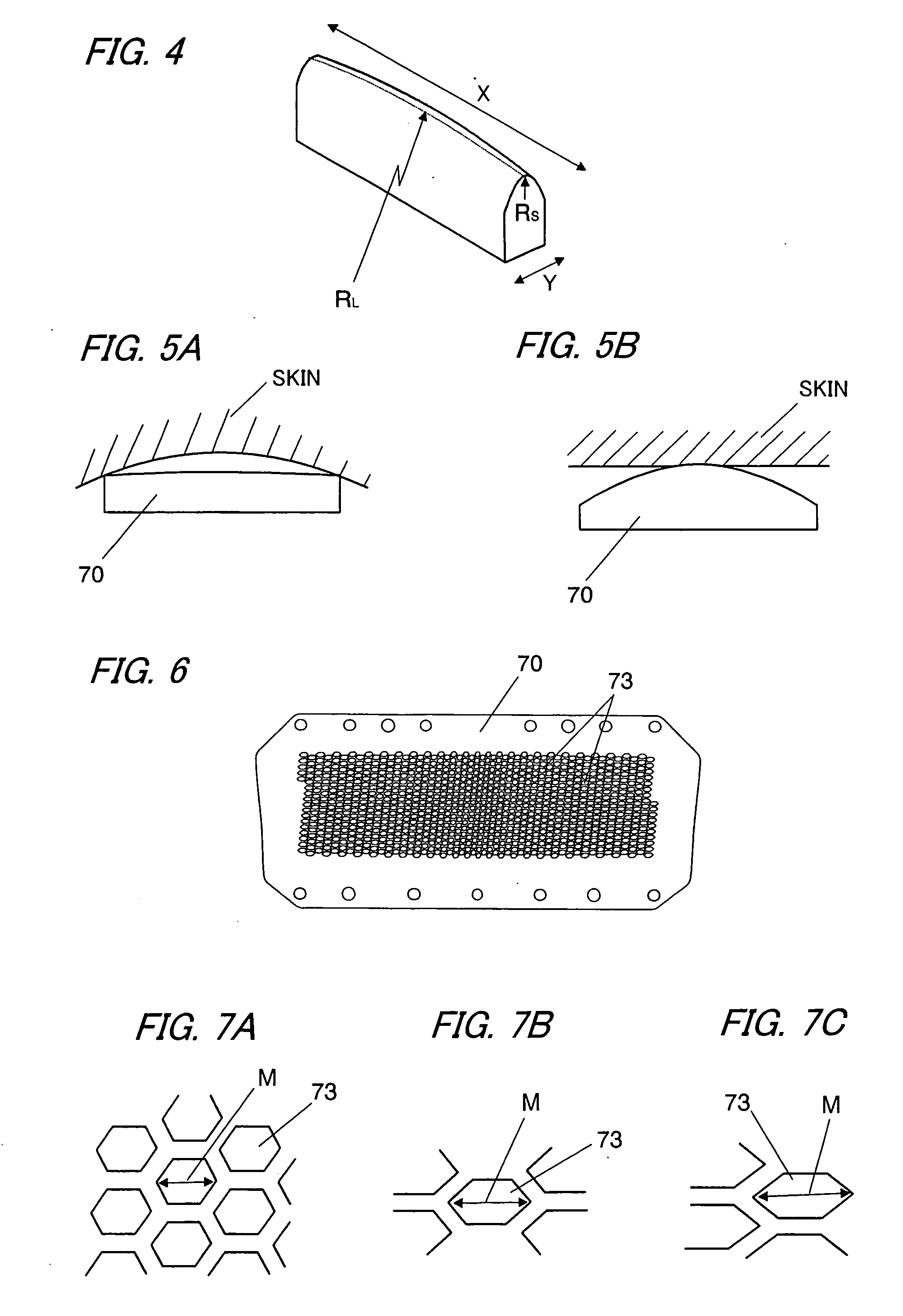
"The present invention provides an electric shaver that can increase the degree of contact between the outer blade foil and a user's skin in various areas of the user's face, such as the jaw, cheek, and nose, while keeping the high degree of contact in the areas near the hand grip. This results in increased shaving efficiency. The electric shaver has a blade head with a C-shaped cross section that has a radius of curvature of 150 mm to 350 mm, which allows for close contact with the user's skin without lopsided pressure distribution. The outer blade foil has a plurality of holes in which hairs are introduced, and the holes are arranged in a pattern that facilitates the introduction of hairs. The holes have a rounded shoulder to prevent skin from coming into the holes excessively and suppress irritating sensation to the skin. The blade head also has two shaving units that are separated from each other at a distance of 0.5 to 2 times the radius of curvature of the transverse arc, which allows for more efficient shaving. The two outer blade foils are supported by the blade head in a floating manner, and each foil can be inclined and depressed independently from the other foil."

Problems solved by technology

However, although the electric shaver of the above publication can have a high degree of contact between the outer blade foil and a user's skin curved concavely, a degree of contact between the outer blade foil and a user's skin which is flat or curved convexly, such as an area under a nose, is low, because the outer blade foil is convexly curved.

Method used


Image

  • Electric shaver
  • Electric shaver
  • Electric shaver

Examples


Embodiment Construction

[0042]Hereinafter, the present invention will be described in more detail with reference to the accompanying drawings.

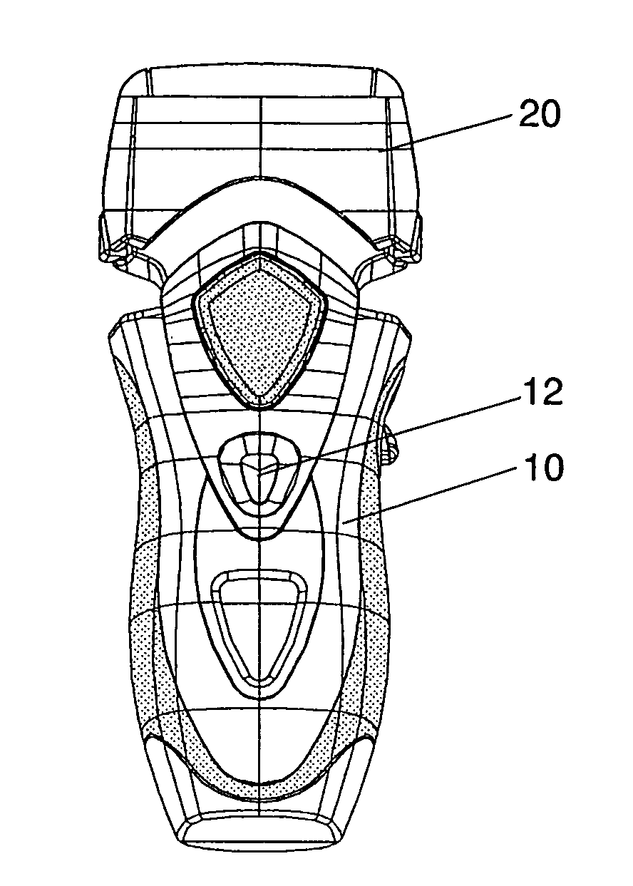
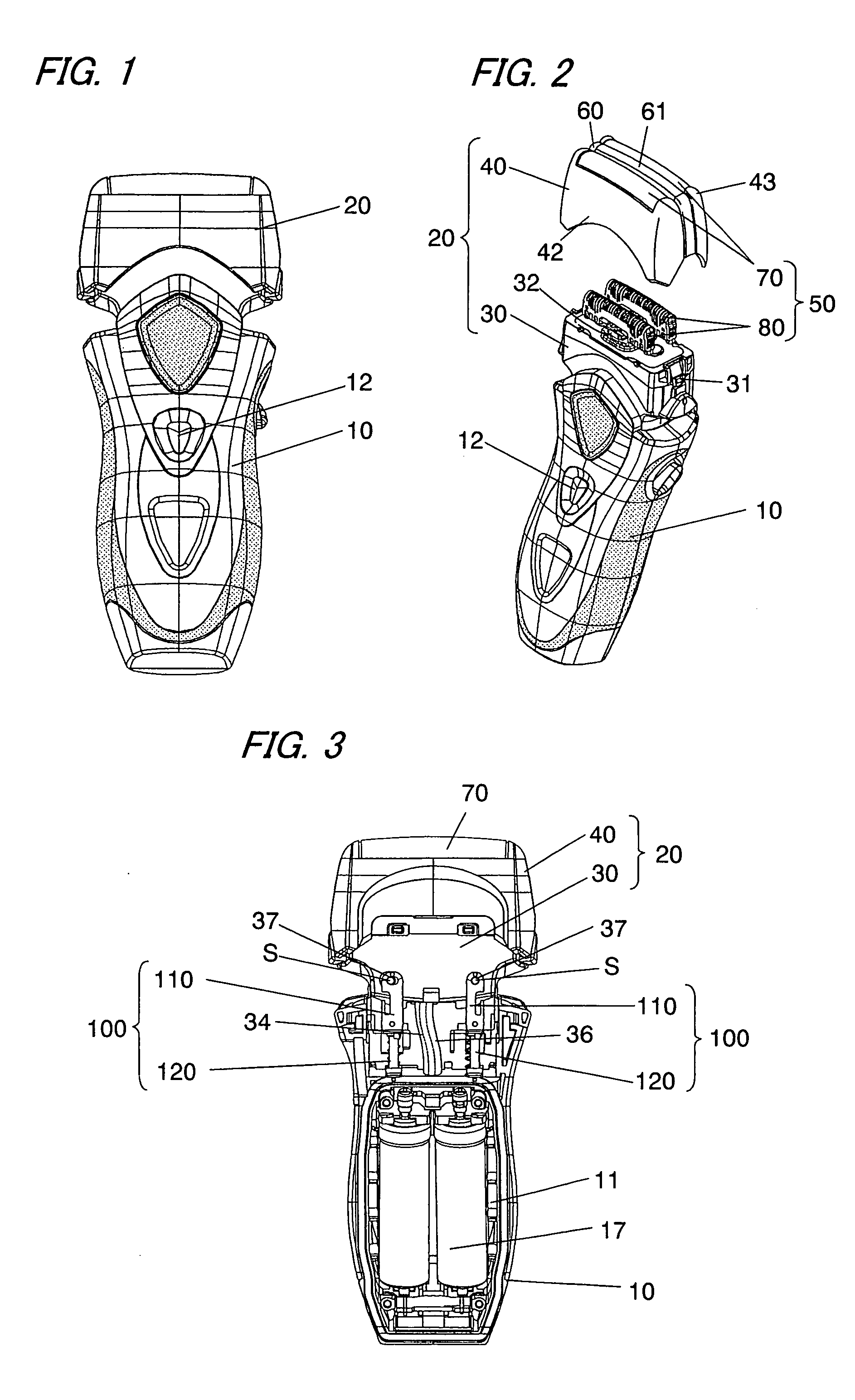
[0043]As shown in FIGS. 1 and 2, an electric shaver in accordance with an exemplary embodiment of the present invention comprises a hand grip 10 configured to be gripped by a user's hand, and a blade head 20 carrying three parallel shaving unit 50 and 60. The blade head 20 is composed of a head block 30 movably supported at the upper end of the hand grip 10, and an outer blade block 40 detachably coupled to the head block 30. Two outer shaving units 50 of these shaving units are designed for shaving relatively short hairs, and each of the outer shaving units 50 comprises an outer blade foil 70 and an inner blade 80 driven in a shearing engagement manner with the outer blade foil 70. A middle shaving unit 60 of these shaving units is designed for shaving relatively long hair, and comprises an outer blade foil 61 and an inner blade 63 (see FIG. 11) driven to do a recip...


PUM


Abstract

An electric shaver including a hand grip 10 configured to be gripped by a user' s hand, and a blade head 20 provided on an upper end of the hand grip. The blade head carries at least one shaving unit 50 comprising an outer blade foil 70 and an inner blade 80 driven in a shearing engagement manner with the outer blade foil. The outer blade foil has a plurality of holes in which hairs are introduced. The outer blade foil is elongated and has a length, and is curved along a width direction to form a generally C-shaped cross section, and is curved convexly and uniformly along its length to have a longitudinal curved outline. A radius of to curvature of the longitudinal curved outline is 150 mm to 350 mm.

Description

BACKGROUND OF THE INVENTION[0001]This application is a divisional application of U.S. application Ser. No. 10 / 578,443, filed May 5, 2006, which is a National Stage of PCT / JP2004 / 016637 filed on Nov. 10, 2004 which claims priority to JP 2003-381464, filed on Nov. 11, 2003, which each is hereby incorporated by reference herein in their entirety as if fully set forth herein.FIELD OF THE INVENTION[0002]The present invention relates to an electric shaver with a net-shaped outer blade foil and an inner blade driven in a shearing engagement manner with the outer blade foil.DESCRIPTION OF THE RELATED ART[0003]In general, an electric shaver has an outer blade foil and an inner blade driven in a shearing engagement manner with the outer blade foil. The outer blade foil is elongated and has a length, and is flat along the length. In this case, a degree of contact between the outer blade foil and a user's skin is high, when a user shaves a flat area of his face, such as a cheek.[0004]On the oth...

Claims


Application Information

Patent Timeline
Patent Type & Authority Applications(United States)
IPC IPC(8): B26B19/02B26B19/28B26B19/04
CPCB26B19/384B26B19/04B26B19/00
Inventor SHIBA, TAKESHINAKAMURA, NARIYOSHISATO, MASAAKIINOUE, TOMOYUKIKOMORI, SHUNSUKEFUKUTANI, MAKOTO
Owner MATSUSHITA ELECTRIC WORKS LTD
Learn More