Wearable protective device

Active Publication Date: 2010-05-27
JSP LTD
View PDF11 Cites 17 Cited by
  • Summary
  • Abstract
  • Description
  • Claims
  • Application Information

AI Technical Summary

Benefits of technology

[0013]The holder may include a bridge portion configured, in use, to fit on a nose bridge of the wearer. The eye shield (e.g. a lower portion of the eye shield) may be connected to the bridge portion of the holder, e.g. by means of at least one fixing device that extends through at least one corresponding aperture in the holder and the eye shield. The fixing device may include a moulded plastic pin. In an alternative embodiment a first portion of a flexible member

Problems solved by technology

This can be inconvenient for the wearer whilst working.
Further, conventional spectacle-type arms for fitting goggles onto the head can be prone to slipping off unintentionally.
This can be particularly problematic when the

Method used


Image

  • Wearable protective device
  • Wearable protective device
  • Wearable protective device

Examples


Example

DETAILED DESCRIPTION OF THE DRAWINGS

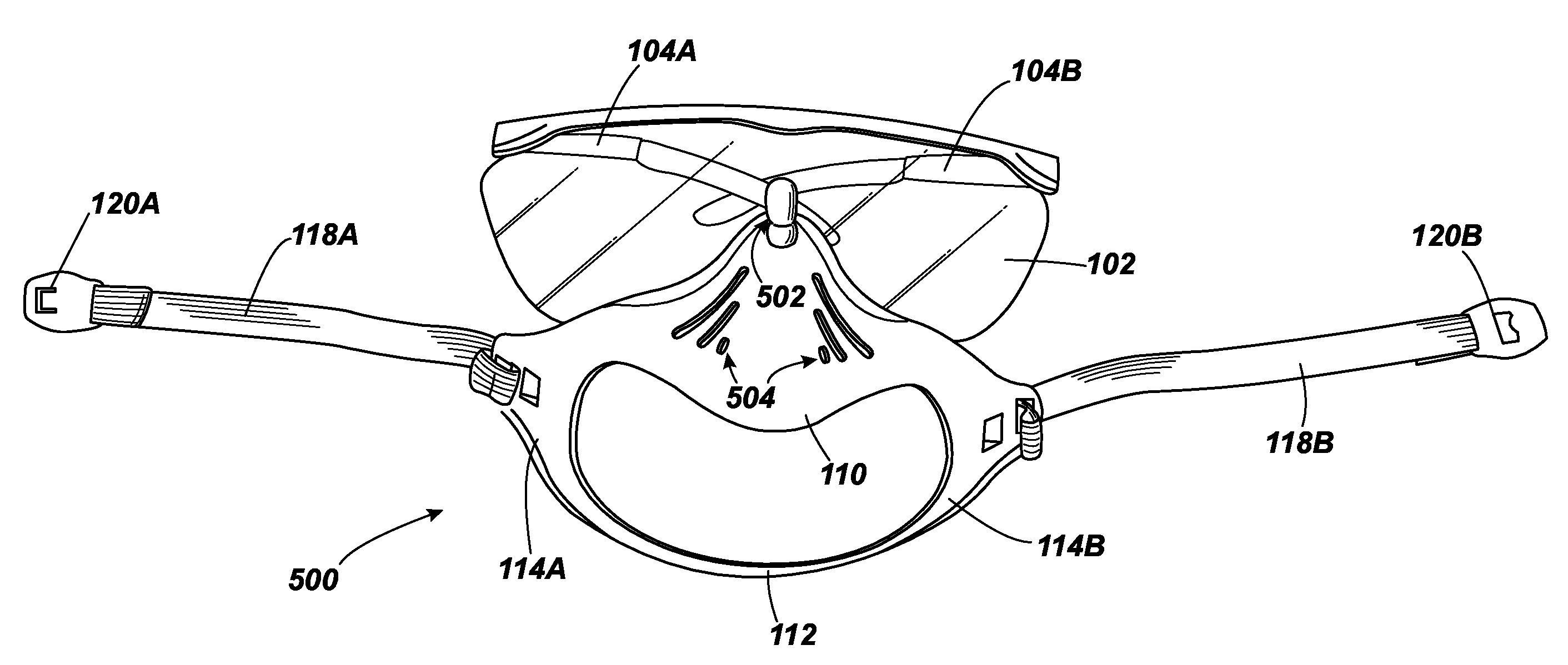
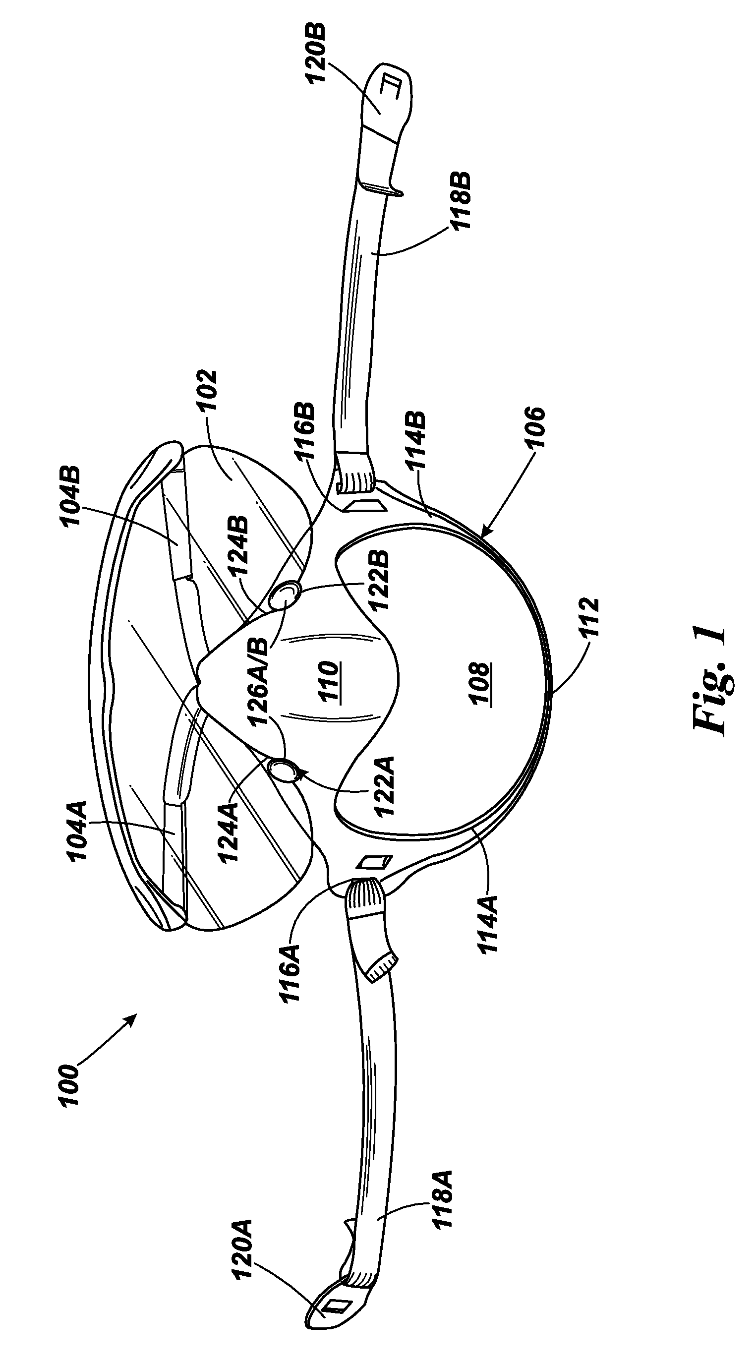
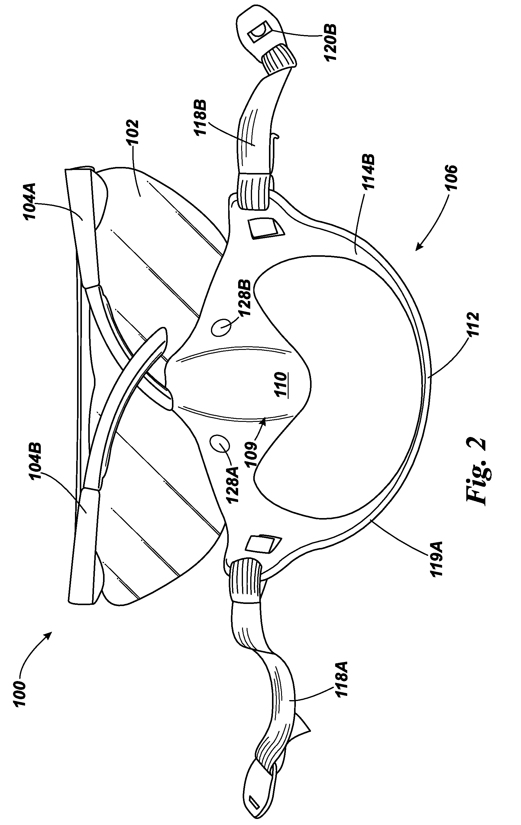
[0029]Referring to FIGS. 1 to 3, a first example of a protective device 100 is shown. The device includes an eye shield including a transparent plastic lens 102 having an upper rim to which a pair of arms 104A, 104B are pivotably connected (the arms are shown in a folded configuration in FIGS. 1 and 2 and in an extended configuration for fitting over the wearer's ears in FIG. 3). It will be understood that the eye shield shown in the Figures is exemplary only and variations are possible. For instance, the shield can be formed of more than one separate lens and an arrangement other than the spectacle-type arm may be provided for fitting the device onto the wearer's head.

[0030]The lens 102 can be formed of a flexible plastic material, such as polycarbonate, polyacetate or acrylic and the arms 104A, 104B and rim / frame of the eye shield may be formed of a semi-flexible plastic material, such as nylon or polypropylene, but it will be understood that ot...


PUM


Abstract

A wearable protective device (100) including an eye shield (102), a holder (106) for a removable breathing filter (400), and an arrangement (104, 118) for fixing the device, in use, to a wearer's head. The eye shield and the holder are integrated or permanently connected together.

Description

[0001]The present application claims priority from U.S. provisional patent application Ser. No. 61 / 182,172 filed on May 29, 2009 and British patent application no. 0821406.6 filed on 22 Nov. 2008.FIELD OF THE INVENTION[0002]The present invention relates to wearable protective devices.BACKGROUND TO THE INVENTION[0003]Many different types of facial masks for protecting the wearer against breathing in dangerous fumes, preventing cross-infection and the like are known. It is also known to wear goggles to protect eyes. Conventionally, breathing masks and goggles are separate items and have to be put on and taken off separately. This can be inconvenient for the wearer whilst working. Further, conventional spectacle-type arms for fitting goggles onto the head can be prone to slipping off unintentionally. This can be particularly problematic when the facemask interferes with the normal fit of the goggles / spectacles. Different facial shapes and different shapes of glasses / goggles can also me...

Claims


Application Information

Patent Timeline
IPC IPC(8): A62B7/00
CPCA41D13/1138A41D13/1184A62B18/084A62B18/02A62B18/082A61F9/029G02C11/00
Inventor JOHNSTONE, CLIVE
Owner JSP LTD
Why Eureka
Try Eureka