Integrated image quality test for imaging system

a technology of imaging system and image quality, applied in the field of integrated image quality test for imaging system, can solve the problems of system out of service, long system unavailability, delay or ignore of repairs or replacements, etc., and achieve the effect of minimizing system downtim

Active Publication Date: 2010-05-27
SYMBOL TECH LLC
View PDF6 Cites 19 Cited by
  • Summary
  • Abstract
  • Description
  • Claims
  • Application Information

AI Technical Summary

Benefits of technology

[0013]Thus, system maintenance personnel are no longer forced to rely on their observation of the captured image, or enter into a lengthy dialog with the system supplier, or purchase special purpose image quality testing software and corresponding computer equipment to execute the testing software, or train in how to operate such testing software and how to interpret the test results. System downtime is minimized, because the testing is performed in the field in situ at the system.

Problems solved by technology

Such image characteristics cannot be determined or measured by observation, except perhaps by specially trained expert personnel, and, as a result, the system maintenance personnel are typically forced to enter into a dialog with the system supplier, often requiring the system to go out of service, typically for a long time, while the quality question is resolved.
The prospect of lengthy system unavailability may force repairs or replacement to be delayed or ignored.
This procedure may be too complex for some maintenance personnel to perform, and, in any event, may cause the system to go out of service for an extended time.

Method used


Image

  • Integrated image quality test for imaging system
  • Integrated image quality test for imaging system
  • Integrated image quality test for imaging system

Examples


Embodiment Construction

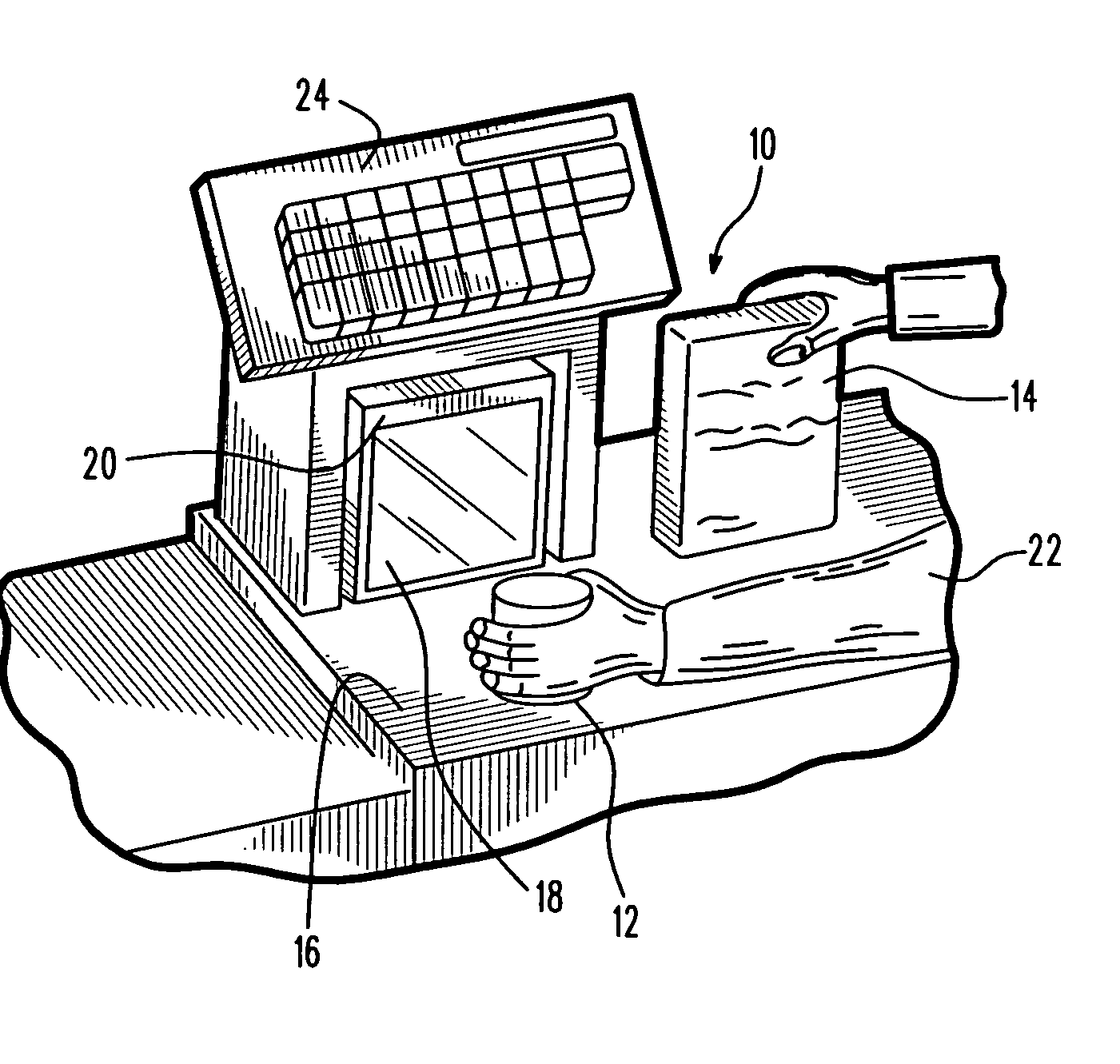
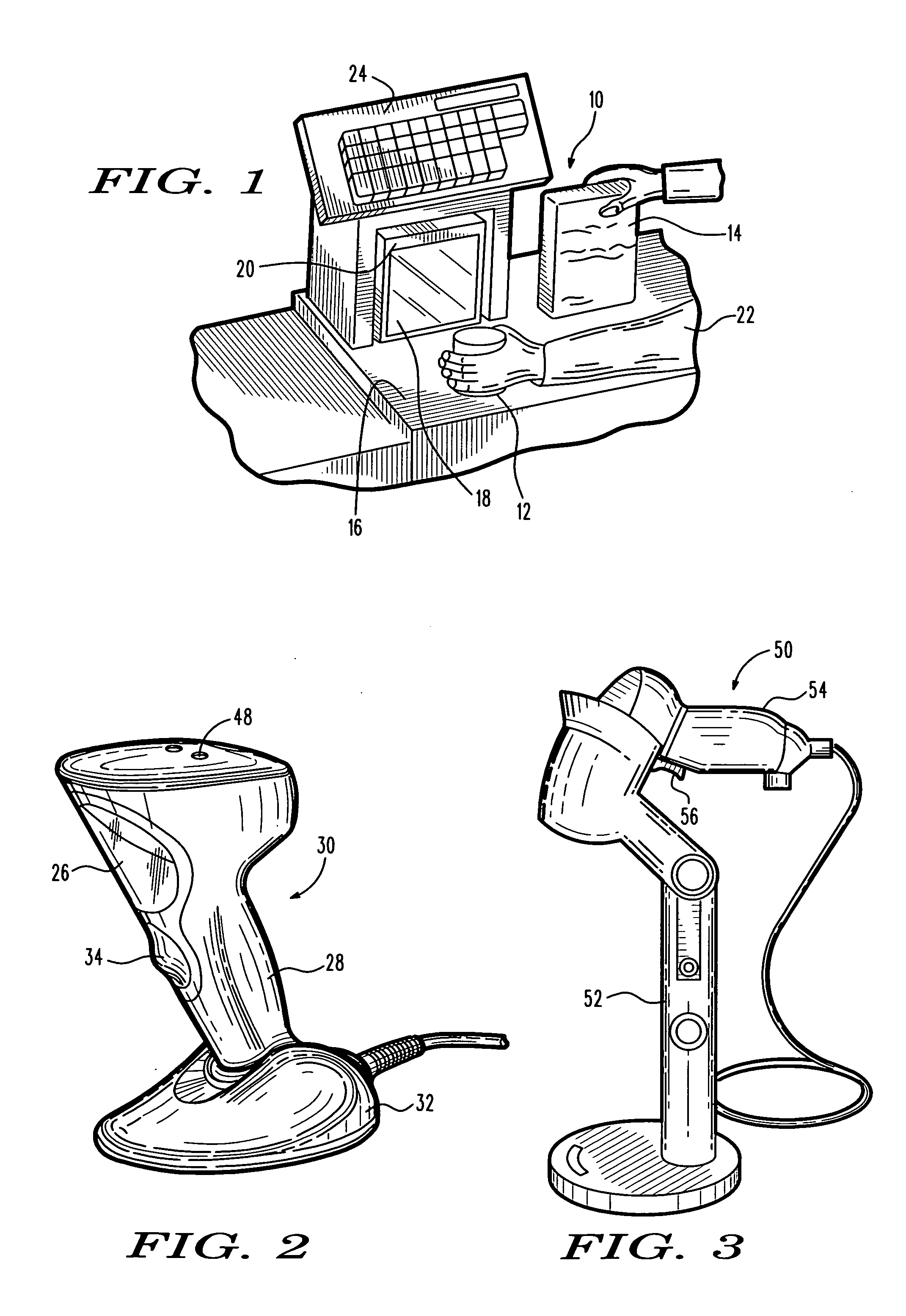
[0025]Reference numeral 10 in FIG. 1 generally identifies a workstation for processing transactions and specifically a checkout counter at a retail site at which products, such as a can 12 or a box 14, each bearing a target symbol, are processed for purchase. The counter includes a countertop 16 across which the products are slid at a swipe speed past, or presented to, a generally vertical or upright planar window 18 of a portable, box-shaped, vertical slot reader or imaging system 20 mounted on the countertop 16. A checkout clerk or operator 22 is located at one side of the countertop, and the imaging system 20 is located at the opposite side. A host computer or cash / credit register 24 is located within easy reach of the operator. The operator 22 can also hold the imaging system 20 in one's hand during imaging.

[0026]Reference numeral 30 in FIG. 2 generally identifies another imaging system having a different configuration from that of imaging system 20. Imaging system 30 also has a...


PUM


Abstract

An imaging system with in-field image quality testing and reporting features, includes a housing, and a solid-state imager having an array of image sensors supported by the housing for capturing return light from a target located in a range of working distances from the housing in an image capture mode of operation, and for capturing return light from a test pattern positioned at a predetermined position in the range of working distances in a test mode of operation different from the image capture mode. An electrical signal indicative of the captured return light is generated in each mode. A memory is supported by the housing for storing a test program for testing image quality. A controller is supported by the housing for processing the electrical signal in the image capture mode, and for accessing the memory to enable the controller to execute the test program in the test mode to test the image quality of the test pattern imaged by the imaging system, and for reporting test results of the image quality of the test pattern.

Description

DESCRIPTION OF THE RELATED ART[0001]Solid-state imaging systems, in both handheld and hands-free modes of operation, have been used in supermarkets, warehouse clubs, department stores, and other kinds of retailers for many years, to electro-optically capture data from various targets, by reading one-dimensional bar code symbols, particularly of the Universal Product Code (UPC) type, each leaving a row of bars and spaces spaced apart along a scan direction, and by reading two-dimensional symbols, such as Code 49, which introduced the concept of vertically stacking a plurality of rows of bar and space patterns in a single symbol as described in U.S. Pat. No. 4,794,239, as well as by capturing images of non-symbol targets, such as persons, places, or things. For example, the image of a consumer, or the consumer's signature, or the consumer's driver's license might be captured for the purpose of age verification in the event that tobacco or alcoholic products are desired to be purchased...

Claims


Application Information

Patent Timeline
Patent Type & Authority Applications(United States)
IPC IPC(8): G06K7/00
CPCG06K7/10722
Inventor BROCK, CHRISTOPHER WARRENCHIN, JONATHANFJELLSTAD, CHRISTOPHERGOREN, DAVID P.MAURO, PATRICKTSI-SHI, DAVIDSTEELE, MICHAEL
Owner SYMBOL TECH LLC
Why Eureka
Try Eureka