
Ceramic orthodontic bracket with improved debonding characteristics

Inactive Publication Date: 2010-05-27
3M INNOVATIVE PROPERTIES CO
View PDF33 Cites 8 Cited by
  • Summary
  • Abstract
  • Description
  • Claims
  • Application Information

AI Technical Summary

Benefits of technology

[0010]The present invention is directed toward a ceramic orthodontic bracket having structure that facilitates detachment of the bracket at the conclusion of treatment. The ceramic bracket includes mesial and distal sections that are detached from the tooth by pivotal movement, and the force needed to initiate pivotal movement is significantly less than the force needed to initiate pivotal movement of mesial and distal sections of ceramic brackets previously known in the art. Yet, the ceramic orthodontic bracket of the present invention can safely withstand the forces normally encountered during the course of orthodontic treatment without substantial risk of inadvertent detachment from the patient's tooth before treatment has been concluded.
[0012]As will be explained in more detail below, the relatively small aspect ratio of the bracket (i.e., the ratio of its overall width to its overall height) increases the likelihood that the configuration of the bracket's base will precisely match the configuration of the patient's tooth surface for a large number of patients. The matching configurations of the bracket base and the tooth surface may help to improve the strength of the adhesive bond between the bracket and the tooth. As a result, the bracket is less likely to unintentionally detach from the tooth during the course of treatment as might otherwise occur, for example, when the patient bites into a relatively hard item of food.

Problems solved by technology

However, orthodontic treatment may lead to increased tooth sensitivity, especially if the course of treatment has extended for a period of several months.
The removal of orthodontic brackets at the conclusion of treatment often results in the application of a force on the adjacent tooth surface.
This force may be relatively small but still considered painful by some patients with sensitive teeth.

Method used


Image

  • Ceramic orthodontic bracket with improved debonding characteristics
  • Ceramic orthodontic bracket with improved debonding characteristics
  • Ceramic orthodontic bracket with improved debonding characteristics

Examples


Embodiment Construction

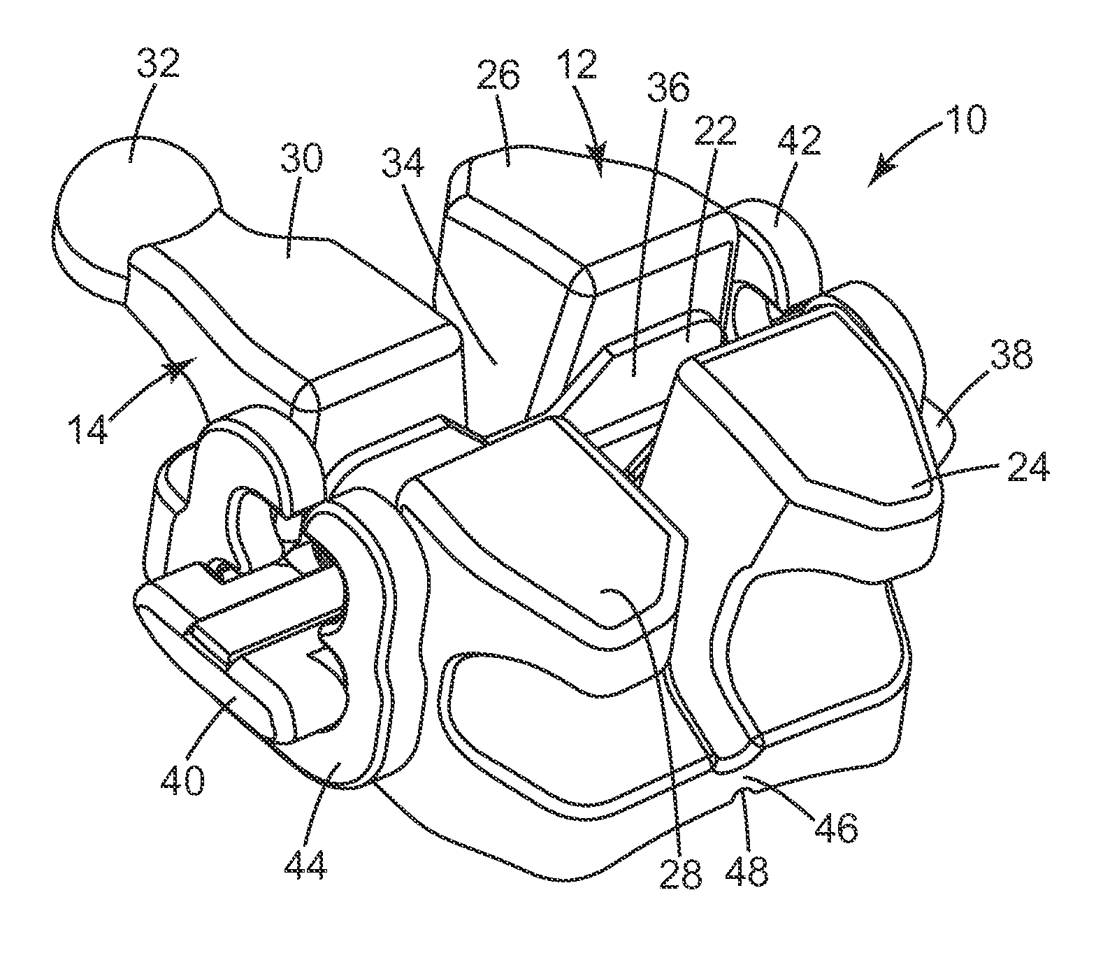
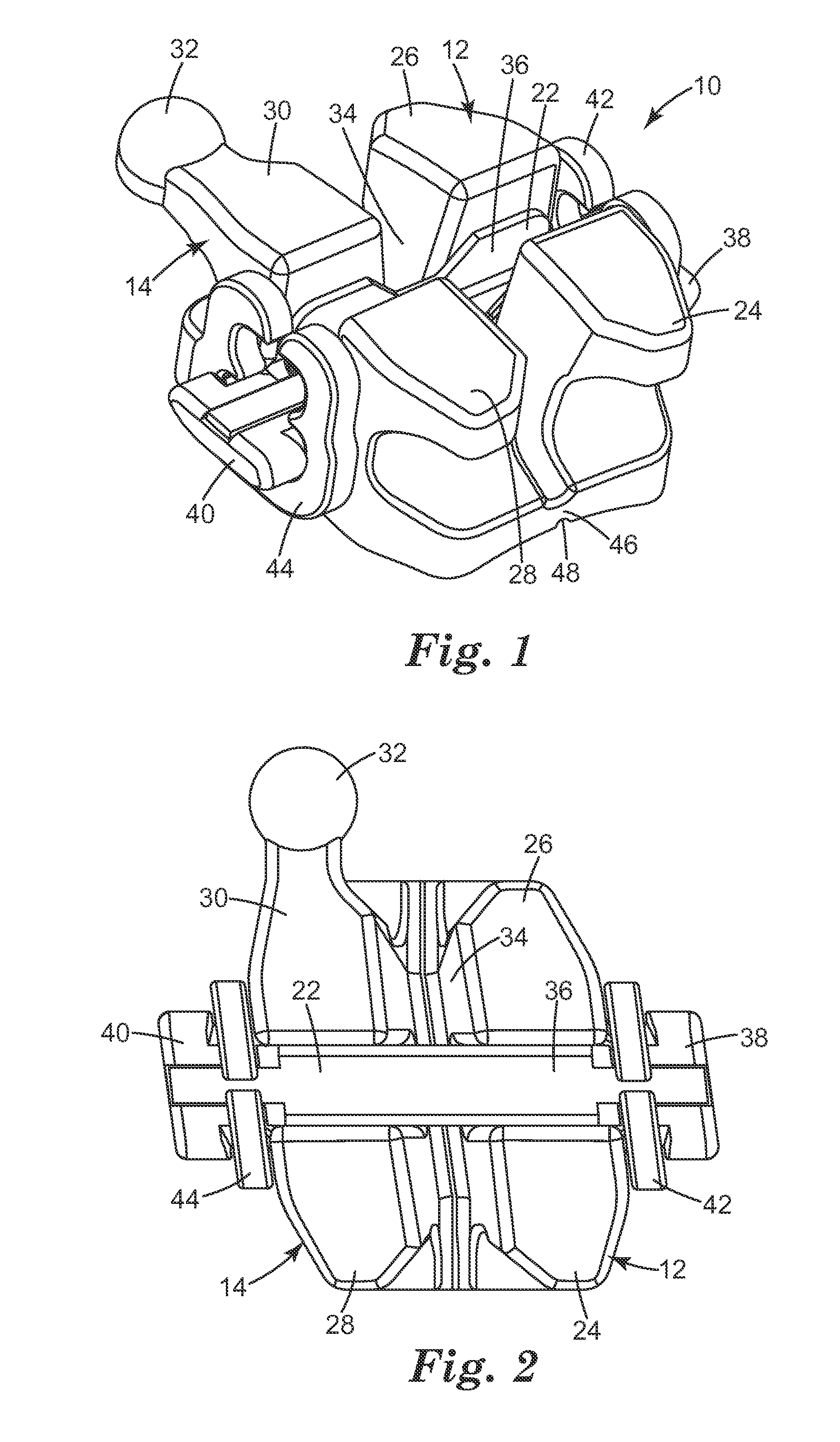
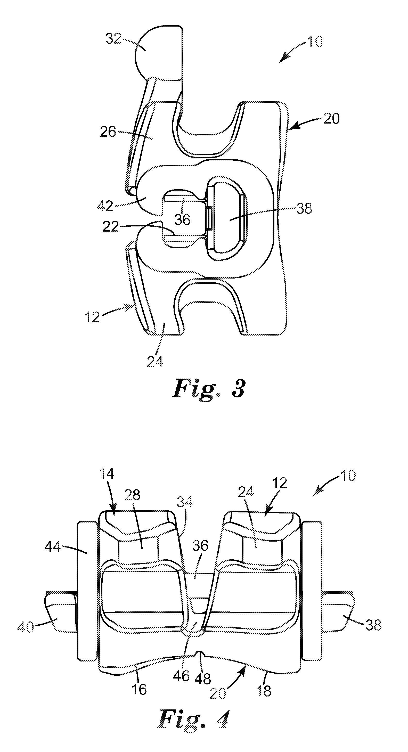
[0027]A ceramic orthodontic bracket constructed in accordance with one embodiment of the present invention is illustrated in FIGS. 1-6 and is broadly designated by the numeral 10. The bracket 10 includes a mesial section 12 and a distal section 14 that is spaced from the mesial section 12. The mesial section 12 includes an external surface 16 and the distal section 14 includes an external surface 18 as shown, for example, in FIGS. 4 and 5.

[0028]The external surfaces 16, 18 together present a base 20 that faces in a lingual direction for bonding the bracket 10 to the enamel surface of a patient's tooth. Preferably, the base 20 has a concave configuration with a compound contour that presents a curved appearance in a reference plane perpendicular to a central mesial-distal reference axis of the bracket 10 as well as in a reference plane perpendicular to a central occlusal-gingival reference axis of the bracket 10. Preferably, the concave compound contour of the base 20 precisely match...


PUM


Abstract

A ceramic bracket has mesial and distal sections that are initially spaced apart from each other by an elongated channel. The bracket is debonded from a patient's tooth at the conclusion of treatment by pivoting one or both of the mesial and distal sections in an arc about a reference axis extending in a direction generally parallel to the channel. The bracket includes a recess that extends across a base of the bracket in generally parallel relationship to the channel. The base of the bracket has an aspect ratio that is less than about 0.95 and enables the bracket to be debonded with less force than might otherwise be necessary.

Description

BACKGROUND OF THE INVENTION[0001]1. Field of the Invention[0002]This invention relates to a ceramic bracket that is used during orthodontic treatment to move a patient's teeth to desired positions. More particularly, the present invention relates to a ceramic orthodontic bracket having structure for facilitating removal of the bracket at the conclusion of treatment.[0003]2. Description of the Related Art[0004]Orthodontic treatment is directed to movement of malpositioned teeth to improved positions in the oral cavity. Orthodontic treatment can greatly enhance the patient's facial appearance, especially in areas near the front of the patient's mouth. Orthodontic treatment can also improve the patient's occlusion so that the teeth function better with each other during mastication.[0005]One type of orthodontic treatment involves the use of a set of appliances and archwires that are commonly known collectively as “braces”. During treatment, tiny slotted appliances known as brackets are...

Claims


Application Information

Patent Timeline
IPC IPC(8): A61C7/28A61C7/14
CPCA61C7/30A61C7/14
Inventor POSPISIL, JIRINA V.
Owner 3M INNOVATIVE PROPERTIES CO
Learn More