
Buffer transfer in a communications network

a communication network and buffer technology, applied in the field of buffer transfer in the communications network, can solve the problems of many losses in the transfer, congestion of other connections sharing the same path, and difficulty in estimating the available buffer transfer capacity

Inactive Publication Date: 2010-05-27
TELEFON AB LM ERICSSON (PUBL)
View PDF5 Cites 9 Cited by
  • Summary
  • Abstract
  • Description
  • Claims
  • Application Information

AI Technical Summary

Benefits of technology

[0010]Current buffer transfer mechanisms are not able to guarantee seamless handover at high data transfer speeds. Unlike in 3G, in the case of LTE or even 4G, the buffer transfer mechanism becomes a bottleneck during high-speed data transfers.

Problems solved by technology

Possible solution for transferring data held in a buffer include possible solutions include User Datagram Protocol (UDP) or Transmission Control Protocol (TCP), but there are problems with using either of these protocols.
It is therefore difficult to estimate the available capacity for a buffer transfer.
Unfortunately the correct rate of this burst is unknown and if it is not estimated correctly, there may be many losses in the transfer.
Furthermore, this technique may cause congestion for other connections sharing the same path.
If for example, the error in the available rate estimation is just 10%, it will cause approximately 10% loss for the transmitted buffer data.
This is a high amount for end-user applications, and is very detrimental to the performance as perceived by the end-user.
TCP, Stream Control Transmission Protocol (SCTP), or custom congestion-controlled UDP may solve the problem of sending buffer data at too high a rate, but these protocols require a large data overhead, making them inefficient for transferring buffer data.
To establish a TCP connection takes too long a time (at least 2 round-trip times are needed before the actual buffer data can be sent).
The result is that the handover interruption time would be dominated by such overheads and not radio protocols.
Keep-alive SCTP, TCP or custom congestion-controlled UDP solves the problem of the connection setup overhead, but when there is no data traffic for a period of time, assumptions made by these protocols about congestion is invalid and not within a guaranteed precision e.g., 10%.
An implication of this is that there may be insufficient available capacity and packets may need to be re-transmitted, possibly causing long time-out and a slow-start.
Again, this leads to the problem that a certain time needed to test for capacity starting from a low data transfer rate.
Current buffer transfer mechanisms are not able to guarantee seamless handover at high data transfer speeds.
If there is no traffic over this connection for some time, the transport protocol has no idea about the congestion state of the transport network, which would normally require measures such as additional extra round-trip times, possible retransmissions, losses, slow-start etc which are all detrimental to the performance of the network and the rate of data transfer between buffers.

Method used


Image

  • Buffer transfer in a communications network
  • Buffer transfer in a communications network
  • Buffer transfer in a communications network

Examples


Embodiment Construction

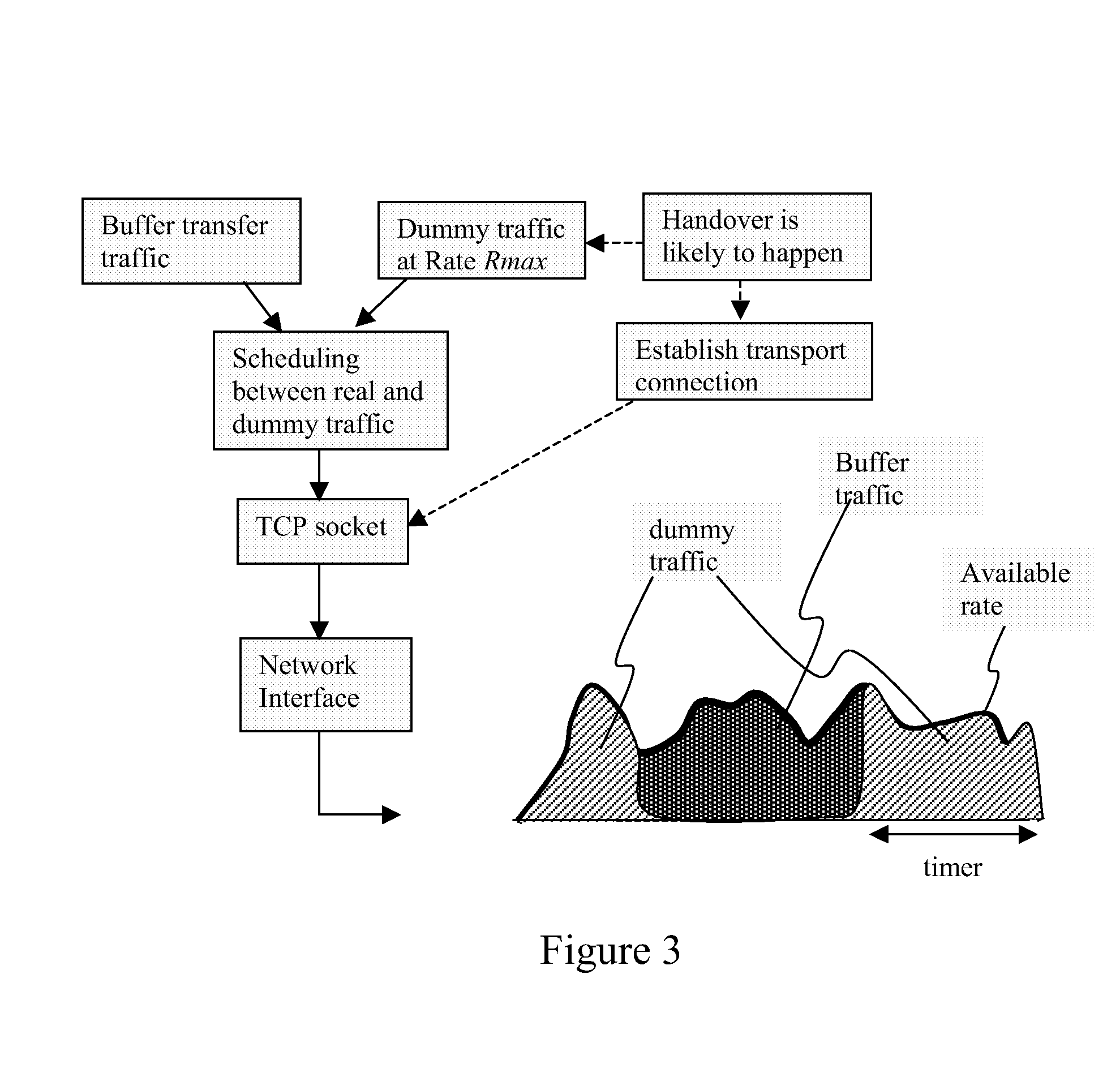
[0033]A semi-continuous transport connection is maintained between two nodes that may be involved in a buffer transfer. When a handover between the nodes is likely to occur, as illustrated in FIG. 3, dummy data is sent over the connection to test the data transfer rate, and once the handover occurs the dummy data is replaced with actual buffer transfer data. Once the buffer transfer data has all been sent and acknowledged, dummy data is again sent over the connection to test the data transfer rate.

[0034]The invention requires the following components, as illustrated in FIG. 4:[0035]A transport protocol server (TPS) 401 including a transport protocol stack, a rate-controlled dummy packet sender, a priority setter and buffer transfer control[0036]Transport protocol client (TPC) 402; and[0037]Transport network equipment with standard transport level priority mechanism enabled (e.g., DiffServ)

[0038]In a mobile communications network, each base station acts as a TPS as well as TPC entity...


PUM


Abstract

A method and apparatus for transferring buffer data from a first network node to a second network node during a mobile handover between cells. In order to improve the speed at which buffer data is transferred during a handover, a connection using a congestion control protocol is established between the two nodes prior to the handover. Dummy data is sent over this connection, in order to approach or reach the available data transfer rate, and at the handover, the dummy data is replaced with buffer data.

Description

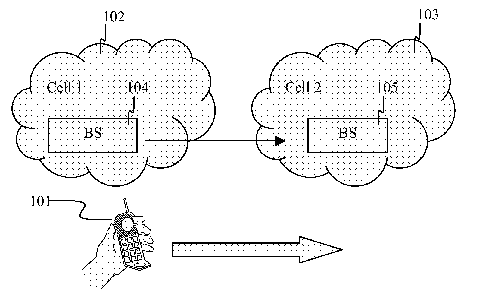
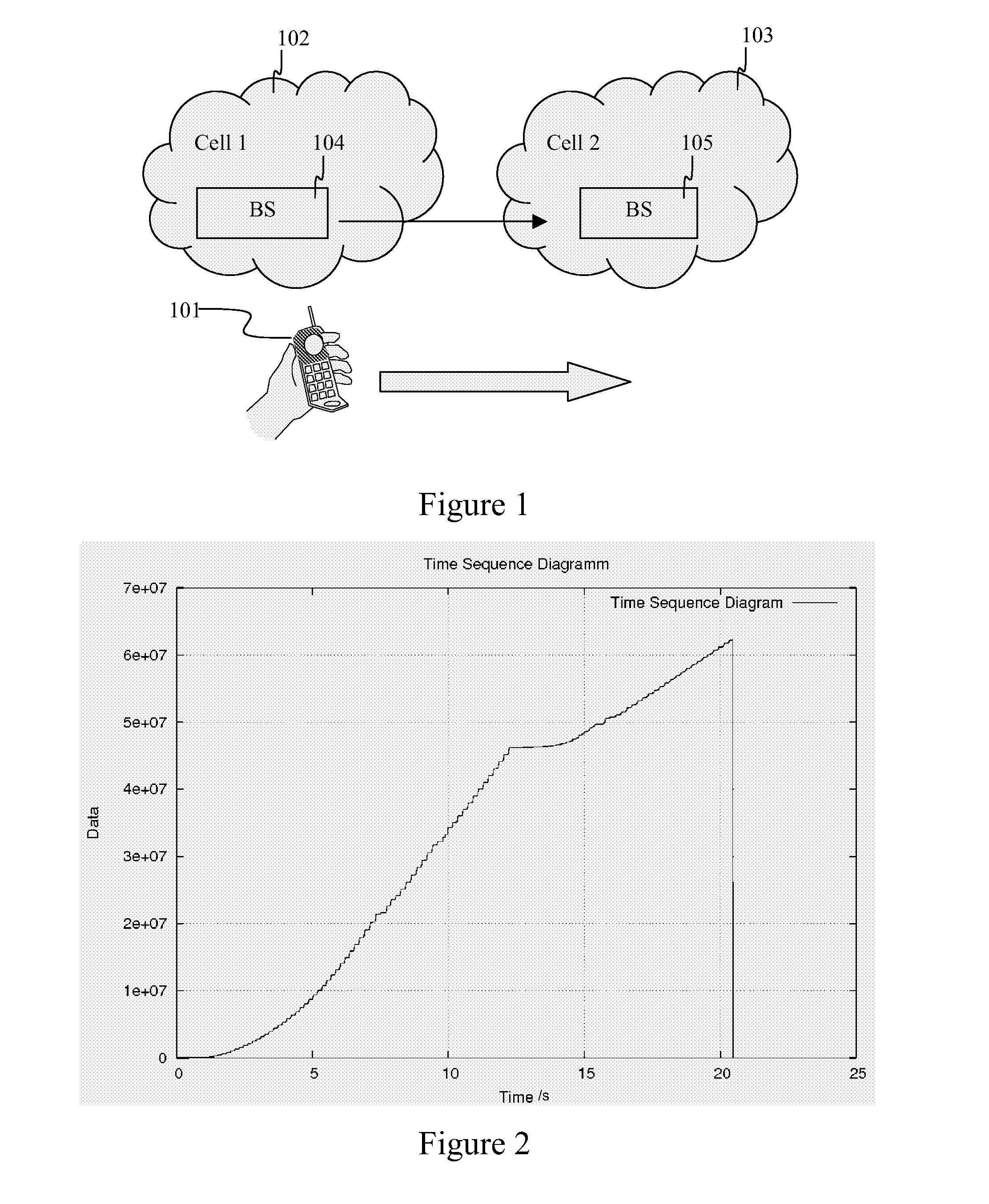
FIELD OF THE INVENTION[0001]The invention relates to buffer transfer in a communications network.BACKGROUND TO THE INVENTION[0002]A cellular mobile access network is a radio network made up of a number of cells, each cell being served by a fixed transmitter. Cells are used to cover different areas in order to provide radio coverage over a wider area than the area of one cell.[0003]As shown in FIG. 1, when a user with mobile equipment 101 moves between the areas covered by adjacent cells 102, 103, a handover must be performed between those cells. A connection between the mobile equipment 101 and the old cell 102 is broken, and a new connection between the mobile equipment 1 and a new cell 3 is established. The cells may comprise a Base Station, Radio Network Controller, or other similar device that has a downlink buffer. Data held in the downlink buffer at the old cell 102 must be transferred to the downlink buffer of the new cell 103.[0004]In 3G networks, this is solved by a special...

Claims


Application Information

Patent Timeline
Patent Type & Authority Applications(United States)
IPC IPC(8): G06F15/16H04W28/14H04W36/08H04W76/02H04W92/20
CPCH04W28/14H04W92/20H04W76/02H04W36/08H04W76/10
Inventor VERES, ANDRAS
Owner TELEFON AB LM ERICSSON (PUBL)
Learn More