Transcritical refrigerant vapor compression system with charge management

a technology of refrigerant vapor compression and charge management, which is applied in the direction of refrigeration components, transportation and packaging, light and heating equipment, etc., can solve the problems of transport refrigerant liquid being undetectedly carried through the suction line, vibration and movement of the refrigerant vapor compression system

Inactive Publication Date: 2010-06-03
CARRIER CORP
View PDF22 Cites 70 Cited by
  • Summary
  • Abstract
  • Description
  • Claims
  • Application Information

AI Technical Summary

Benefits of technology

[0008]A transcritical refrigerant vapor compression system having improved refrigerant charge management includes a compression device, a refrigerant heat rejection heat exchanger, a refrigerant heat absorption heat exchanger, and a refrigerant-to-refrigerant heat exchanger economizer and a flash tank disposed in a primary refrigerant circuit in series refrigerant flow relationship intermediate a refrigerant heat rejection heat exchanger and a refrigerant heat absorption heat exchanger. A primary expansion valve interdisposed in the refrigerant circuit in operative association with and upstream of the refrigerant heat absorption heat exchanger and a secondary expansion valve interdisposed in the refrigerant circuit in operative association and upstream of the flash tank. A refrigerant vapor bypass line establishes refrigerant vapor flow communication between the flash tank and a suction pressure portion of the primary refrigerant circuit downstream of the refrigerant heat absorption heat exchanger. A bypass flow control valve having an open position and a closed position is interdisposed in the refrigerant vapor bypass line for controlling the flow of refrigerant vapor through the refrigerant vapor bypass line.

Problems solved by technology

Additionally, transport refrigerant vapor compression systems are subject to vibration and movements not experienced by stationary refrigerant vapor compression systems.
Thus, the use of a conventional refrigerant accumulator in the suction line upstream of the compressor suction inlet to store excess refrigerant liquid would be subject to sloshing during movement that could result in refrigerant liquid being undesirably carried through the suction line into the compressor via the suction inlet thereto.

Method used


Image

  • Transcritical refrigerant vapor compression system with charge management
  • Transcritical refrigerant vapor compression system with charge management
  • Transcritical refrigerant vapor compression system with charge management

Examples


Embodiment Construction

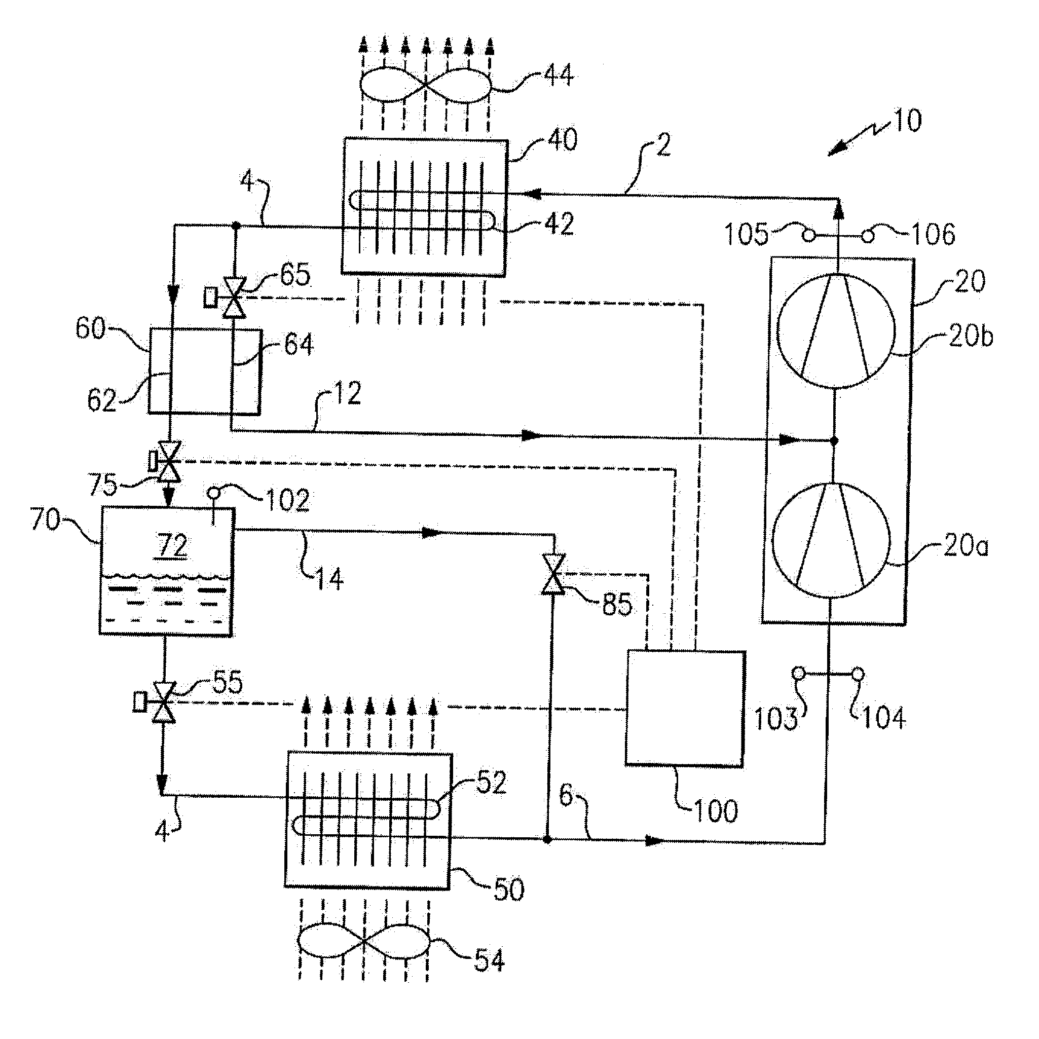
[0017]Referring now to FIG. 1, there is depicted an exemplary embodiment of a transcritical refrigerant vapor compression system 10 suitable for use in a transport refrigeration system for refrigerating air supplied to a temperature controlled cargo space of a truck, trailer, container or the like for transporting perishable and frozen goods. The refrigerant vapor compression system 10 is also suitable for use in conditioning air to be supplied to a climate controlled comfort zone within a residence, office building, hospital, school, restaurant or other facility. The refrigerant vapor compression system could also be employed in refrigerating air supplied to display cases, merchandisers, freezer cabinets, cold rooms or other perishable and frozen product storage areas in commercial establishments.

[0018]The transcritical refrigerant vapor compression system 10 includes a multi-stage compression device 20, a refrigerant heat rejection heat exchanger 40, also referred to herein as a g...


PUM


Abstract

A refrigerant vapor compression system includes a refrigerant-to-refrigerant heat exchanger economizer and a flash tank disposed in series refrigerant flow relationship in the refrigerant circuit intermediate a refrigerant heat rejection heat exchanger and a refrigerant heat absorption heat exchanger. A primary expansion valve is interdisposed in the refrigerant circuit upstream of the refrigerant heat absorption heat exchanger and a secondary expansion valve is interdisposed in the refrigerant circuit upstream of the flash tank. The flash tank functions as a refrigerant charge storage reservoir wherein refrigerant expanded from a supercritical pressure to subcritical pressure separates into liquid and vapor phases. A refrigerant vapor bypass line is provided to return refrigerant vapor from the flash tank to the refrigerant circuit downstream of the refrigerant heat absorption heat exchanger. The primary expansion valve and a flow control valve interdisposed in the refrigerant vapor bypass provide refrigerant charge management.

Description

FIELD OF THE INVENTION [0001]This invention relates generally to refrigerant vapor compression systems and, more particularly, to refrigerant charge management in a refrigerant vapor compression system operating in a transcritical cycle.BACKGROUND OF THE INVENTION[0002]Refrigerant vapor compression systems are well known in the art and commonly used for conditioning air to be supplied to a climate controlled comfort zone within a residence, office building, hospital, school, restaurant or other facility. Refrigerant vapor compression systems are also commonly used in refrigerating air supplied to display cases, merchandisers, freezer cabinets, cold rooms or other perishable / frozen product storage area in commercial establishments.[0003]Refrigerant vapor compression systems are also commonly used in transport refrigeration systems for refrigerating air supplied to a temperature controlled cargo space of a truck, trailer, container or the like for transporting perishable / frozen items ...

Claims


Application Information

Patent Timeline
Patent Type & Authority Applications(United States)
IPC IPC(8): F25B1/00F25B41/00F25B43/00
CPCF25B1/10F25B9/008F25B2309/061F25B2400/13F25B2400/23F25B2700/21152F25B2700/19F25B2700/1931F25B2700/1933F25B2700/21151F25B2600/2509B60H1/3228
Inventor MITRA, BISWAJITCHEN, YU H.
Owner CARRIER CORP
Why Eureka
Try Eureka