Ejector cycle system

a technology of ejector cycle and cycle system, which is applied in the direction of refrigeration components, transportation and packaging, light and heating apparatus, etc., can solve the problems of insufficient improvement of heating performance, difficult to be suitable for heating operation, and difficult to improve heat exchange performance in each of the interior heat exchanger and the exterior heat exchanger

Inactive Publication Date: 2003-04-22
DENSO CORP
View PDF6 Cites 72 Cited by
  • Summary
  • Abstract
  • Description
  • Claims
  • Application Information

AI Technical Summary

Benefits of technology

According to a first aspect of the present invention, in an ejector cycle system with an ejector having a nozzle and a pressure-increasing portion, the flow direction of refrigerant, flowing through at least one of an exterior heat exchanger and an interior heat exchanger in a cooling operation where heat is radiated from a compartment to an outside, is identical to that in a heating operation where heat is radiated from the outside to the compartment. Accordingly, heat-exchanging performance can be effectively improved in at least one of the exterior and interior heat exchangers. Because the flow direction of refrigerant flowing through at least one of the exterior heat exchanger and the interior heat exchanger can be set identical in both the cooling operation and the heating operation, a special member such as a refrigerant distribution member (e.g., a throttle) can be disposed at a refrigerant inlet side in each of the exterior heat exchanger and the interior heat exchanger, for example. In this case, refrigerant-distribution performance in each of the exterior heat exchanger and the interior heat exchanger can be improved.
According to a second aspect of the present invention, in an ejector cycle system having the ejector, a decompression unit for decompressing refrigerant flowing from the interior heat exchanger is disposed. In addition, in the cooling operation for cooling the compartment, the high-pressure side refrigerant is decompressed by the ejector. On the other hand, in the heating operation for heating the compartment, the high-pressure side refrigerant is decompressed by the decompression unit. Accordingly, in the heating operation, the pressure of refrigerant to be sucked into a compressor can be made lower, and the temperature of refrigerant discharged from the compressor is increased. As a result, heating performance can be improved in the heating operation, while cooling performance is improved in the cooling operation.

Problems solved by technology

In this case, if a dimension of a refrigerant passage in each of the interior heat exchanger and the exterior heat exchanger is set to be suitable for the cooling operation, it is difficult to be suitable for the heating operation.
Accordingly, it is difficult to improve heat-exchanging performance in each of the interior heat exchanger and the exterior heat exchanger, for both the cooling operation and the heating operation.
Accordingly, in the heating operation, heating performance cannot be sufficiently improved.

Method used


Image

  • Ejector cycle system
  • Ejector cycle system
  • Ejector cycle system

Examples


first embodiment

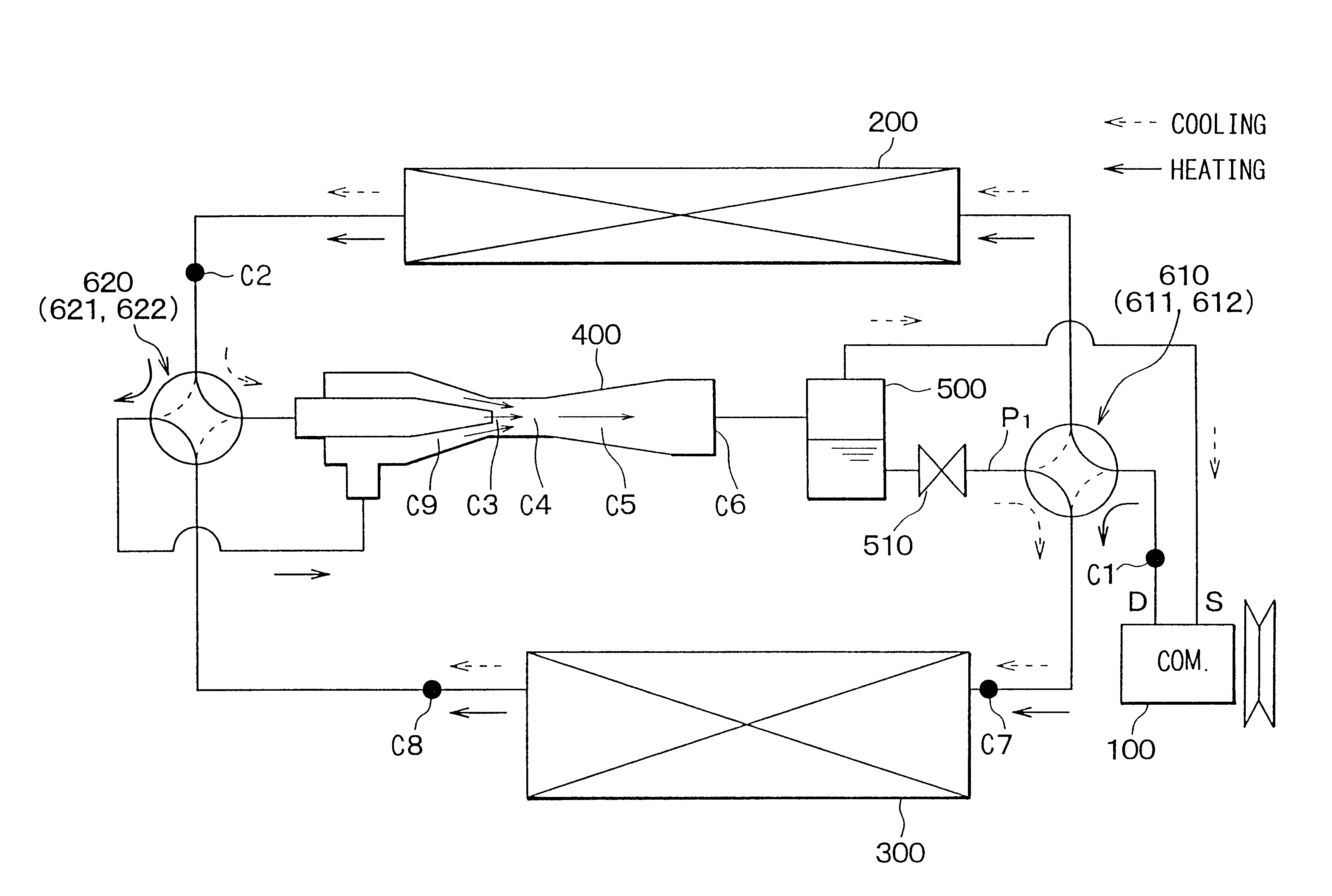
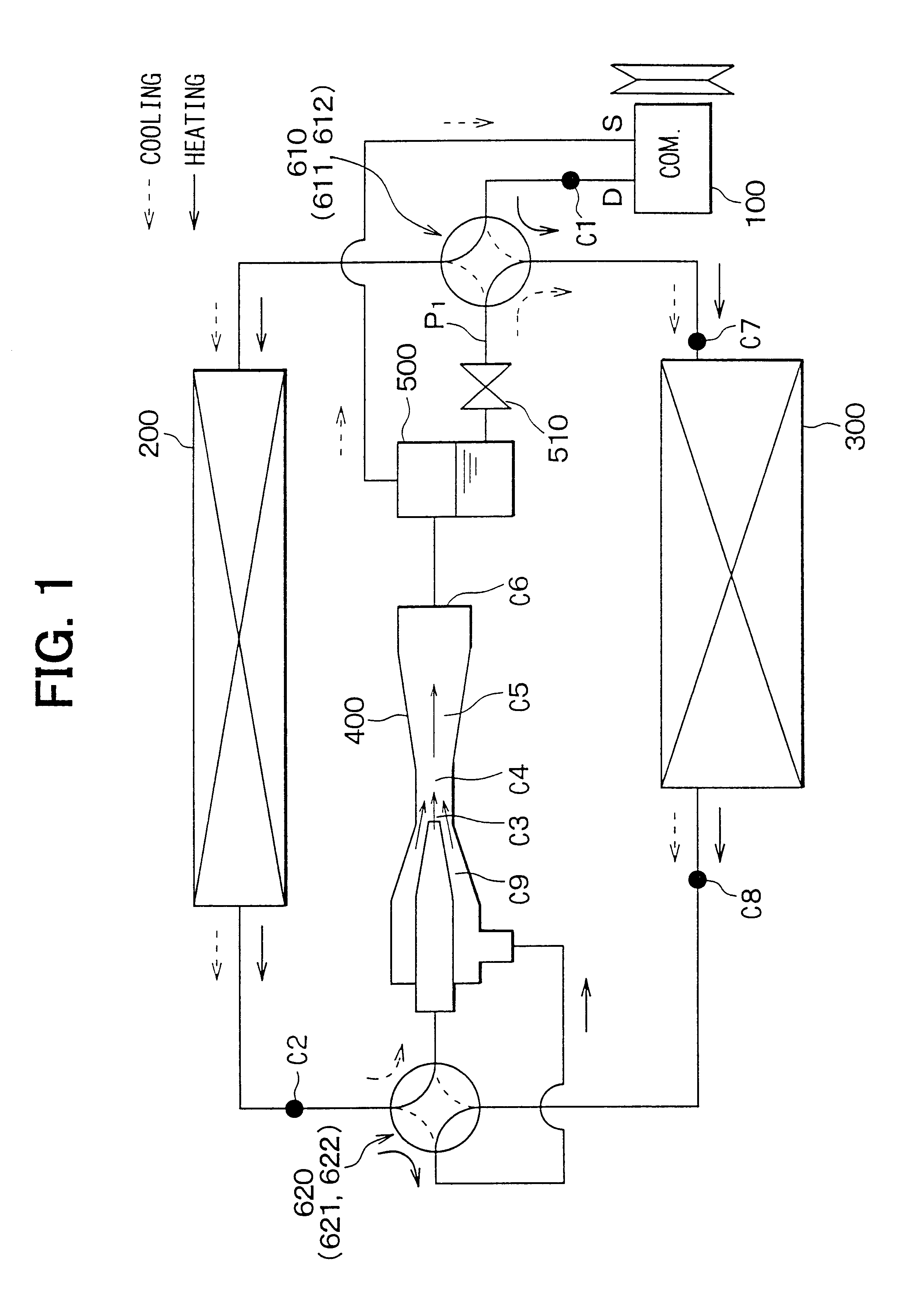
A first preferred embodiment of the present invention will be now described with reference to FIGS. 1-3. In the first embodiment, an ejector cycle system of the present invention is typically used for a vehicle air conditioner.

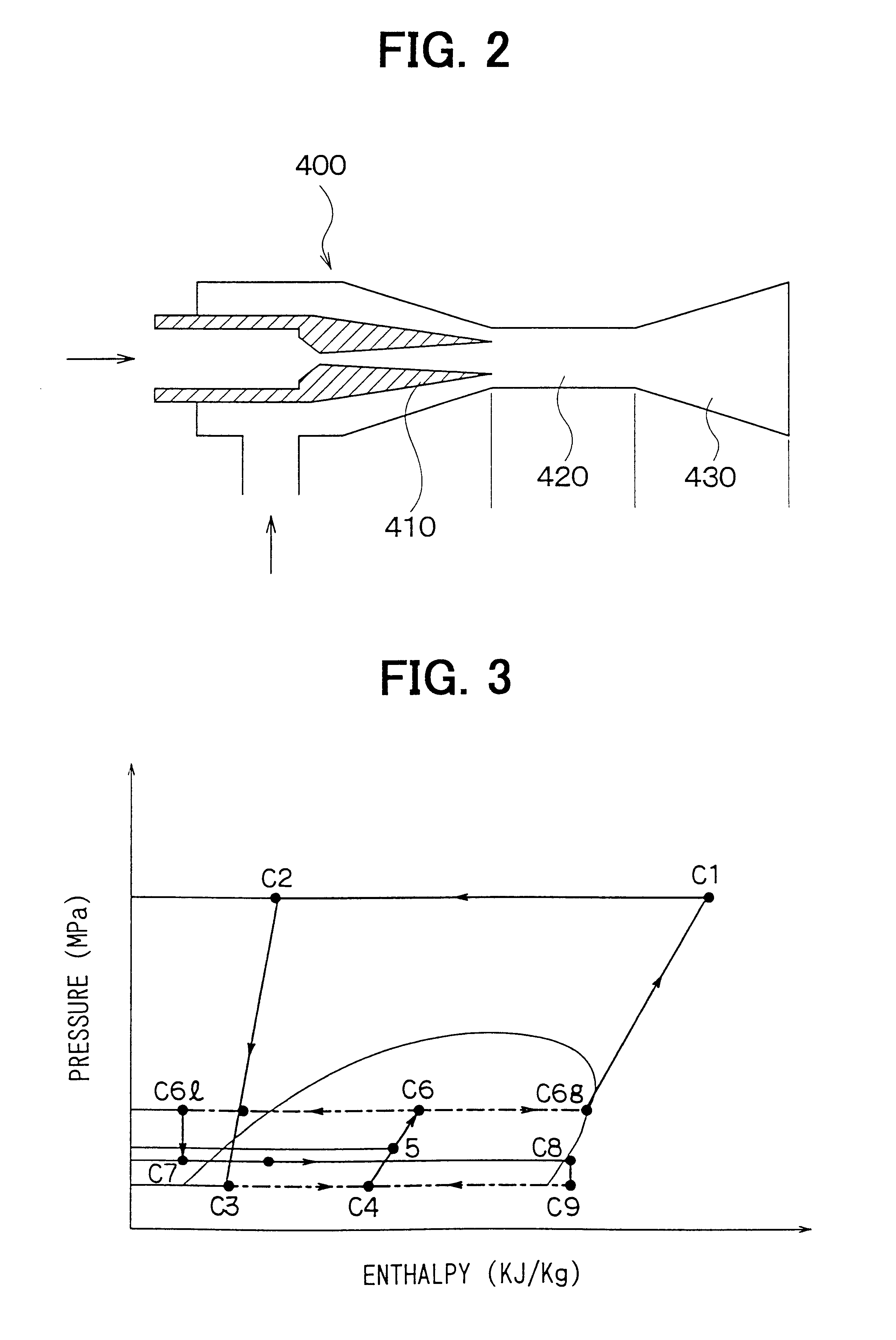
As shown in FIG. 1, a compressor 100 is driven by a driving source such as a vehicle engine (not shown) to suck and compress refrigerant (e.g., carbon dioxide in the first embodiment). In an exterior heat exchanger 200, refrigerant in the ejector cycle system is heat-exchanged with air (outside air) outside a passenger compartment. In an interior heat exchanger 300, refrigerant in the ejector cycle system is heat-exchanged with air to be blown into a passenger compartment. An ejector 400 decompresses and expands refrigerant at a high pressure side so that gas refrigerant evaporated at a low pressure side is sucked therein, and converts an expansion energy to a pressure energy to increase a pressure of refrigerant to be sucked into the compressor 100.

As shown i...

second embodiment

Specifically, as shown in FIG. 4, a solenoid two-way valve 630 for opening and closing a refrigerant passage is provided at a refrigerant instruction side of the nozzle 410 of the ejector 400. Further, a decompression device (e.g., a fixed restrictor in the second embodiment) 640 is provided in a refrigerant passage through which the exterior heat exchanger 200 is connected to a refrigerant outlet side of the interior heat exchanger 300. A three-way valve 631 is provided in a refrigerant passage to switch any one of a case where refrigerant flows from the interior heat exchanger 300 into the mixing portion 420 of the ejector 400 and a case where refrigerant flows from the interior heat exchanger 300 to the fixed restrictor 640.

Next, the cooling operation and the heating operation of the ejector cycle system according to the second embodiment will be now described.

In the cooling operation, refrigerant discharged from the compressor 100 flows through the first four-way valve 610, the ...

third embodiment

Accordingly, in the cooling operation of the ejector cycle system of the third embodiment, refrigerant discharged from the compressor 100 flows through the first four-way valve 610, the exterior heat exchanger 200, the three-way valve 633, the ejector 400, the first four-way valve 610 and the gas-liquid separator 500 in this order, and is introduced into the compressor 100. Further, liquid refrigerant from the gas-liquid separator 500 circulates the restriction device 510, the three-way valve 632, the interior heat exchanger 300, the ejector 400 (the mixing portion 420, the diffuser 430), the first four-way valve 610 and the gas-liquid separator 500 in this order.

On the other hand, in the heating operation, refrigerant from the compressor 100 circulates the first four-way valve 610, the diffuser 430, the mixing portion 420, the interior heat exchanger 300, the three-way valve 632, the fixed restrictor 640, the three-way valve 633, the exterior heat exchanger 200, the first four-way ...


PUM


Abstract

In an ejector cycle system, high-pressure side refrigerant is decompressed by an ejector in cooling operation for cooling a compartment, and is decompressed by a fixed restrictor in heating operation for heating the compartment. Therefore, in the heating operation, the pressure of refrigerant to be sucked into a compressor can be made lower, and the temperature of refrigerant discharged from the compressor is increased. Alternatively, in the cooling operation, a flow direction of refrigerant flowing through at least one of an exterior heat exchanger and an interior heat exchanger is identical to that in the heating operation.

Description

This application is related to Japanese Patent Applications No. 2001-57260 filed on Mar. 1, 2001, and No. 2001-208011 filed on Jul. 9, 2001, the contents of which are hereby incorporated by reference.1. Field of the InventionThe present invention relates to an ejector cycle system having an ejector. The ejector sucks gas refrigerant evaporated at a lower pressure side, and increases a pressure of refrigerant to be sucked into a compressor by converting an expansion energy to a pressure energy.2. Description of Related ArtIn a conventional ejector cycle system described in JP-U-55-26273, refrigerant-flowing direction in each of an interior heat exchanger and an exterior heat exchanger during a cooling operation is opposite to that during a heating operation. In this case, if a dimension of a refrigerant passage in each of the interior heat exchanger and the exterior heat exchanger is set to be suitable for the cooling operation, it is difficult to be suitable for the heating operatio...

Claims


Application Information

Patent Timeline
Patent Type & Authority Patents(United States)
IPC IPC(8): F25B41/00F25B13/00F25B9/00F25B1/00
CPCF25B9/008F25B13/00F25B41/00F25B2341/0012F25B2309/061B60H2001/3298
Inventor TAKEUCHI, HIROTSUGUYAMANAKA, YASUSHIOSHITANI, HIROSHI
Owner DENSO CORP
Why Eureka
Try Eureka