Vehicular heat pump system

a heat pump and vacuum technology, applied in heat pumps, lighting and heating apparatuses, refrigeration components, etc., can solve the problems of deteriorating heating performance, reducing the mileage of electric vehicles or hybrid vehicles, and reducing the indoor discharge temperature from 5° c. to 10° c., so as to improve cooling performance, improve cooling performance, and minimize the effect of indoor discharge temperature chang

Active Publication Date: 2020-08-25
HANON SYST
View PDF26 Cites 2 Cited by
  • Summary
  • Abstract
  • Description
  • Claims
  • Application Information

AI Technical Summary

Benefits of technology

[0020]According to an embodiment of the present invention, because the vehicular heat pump system includes the chiller for exchanging heat among coolant which circulates through electronic units 200 of a vehicle, a refrigerant which is discharged from an outdoor heat exchanger and flows in a first bypass line R1, and a refrigerant which is discharged from an indoor heat exchanger, the heat pump system may increase a refrigerant flow rate and improving cooling performance due to an increase of subcooling while the refrigerant discharged from the indoor heat exchanger is second cooled in the outdoor heat exchanger after being first cooled in the chiller in the air-conditioning mode, increase the refrigerant flow rate because the refrigerant discharged from the indoor heat exchanger secures subcooling in the chiller in the heat pump mode, and improve heating performance because the refrigerant discharged from the outdoor heat exchanger receives additional heat source from the chiller.
[0021]Furthermore, the vehicular heat pump system according to the present invention may minimize a change in indoor discharge temperature by a lack of heat sources by securing additional heat source from the chiller even in a defrosting mode due to frosting of the outdoor heat exchanger.

Problems solved by technology

As described above, because the operation of the heat pump system is stopped when frosting is generated, it deteriorates heating performance.
In this instance, when an electric heater is operated for heating, consumption of electric power increases and it causes decrease in mileage of electric vehicles or hybrid vehicles.
However, the conventional heat pump system has a disadvantage in that indoor discharge temperature lowers about 5° C. to 10° C. because the heat pump system uses just the waste heat of the electronic units of the vehicle as a heat source when frosting is formed on the surface of the outdoor heat exchanger, and in that a PTC heater must be additionally operated in order to keep indoor temperature.
Moreover, the conventional heat pump system has another disadvantage in that a refrigerant flow rate is reduced because the refrigerant discharged from the indoor heat exchanger is not condensed sufficiently, so it causes deterioration in heating performance and cooling performance.

Method used


Image

  • Vehicular heat pump system
  • Vehicular heat pump system
  • Vehicular heat pump system

Examples


Embodiment Construction

[0030]Reference will be now made in detail to the preferred embodiment of the present invention with reference to the attached drawings.

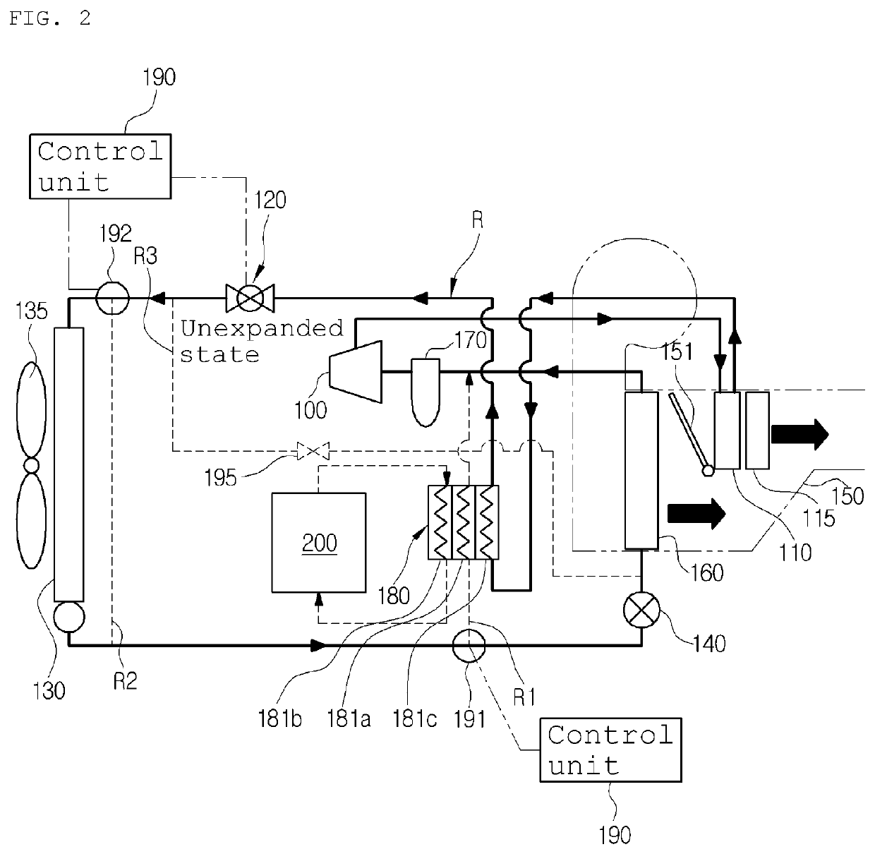
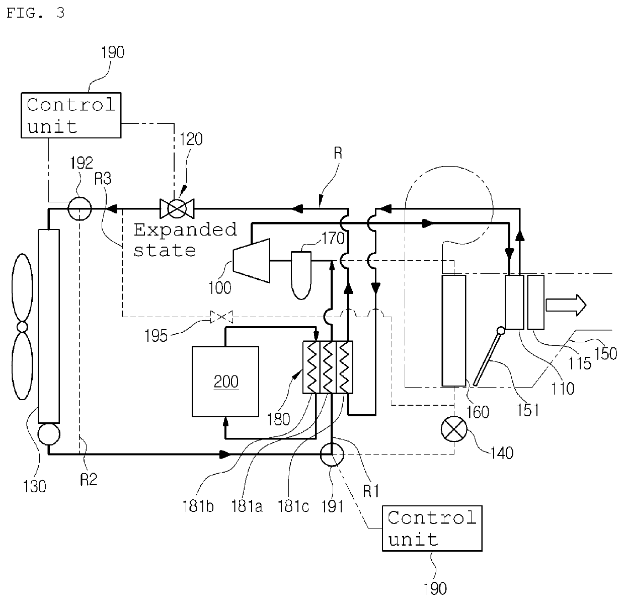
[0031]First, a vehicular heat pump system according to the present invention includes a compressor 100, an indoor heat exchanger 110, a first expansion valve 120, an outdoor heat exchanger 130, a second expansion valve 140, and an evaporator 160 which are connected on a refrigerant circulation line R in order, and is preferably applied to electric vehicles or hybrid vehicles.

[0032]Moreover, on the refrigerant circulation line R, a first bypass line R1 bypassing the second expansion valve 140 and the evaporator 160 and a second bypass line R2 bypassing the outdoor heat exchanger 130 are connected and mounted in parallel. A first direction changing valve 191 is mounted at a branch point of the bypass line R1, a second direction changing valve 192 is mounted at a branch point of the second bypass line R2, and a chiller 180 is mounted on the first bypas...


PUM


Abstract

The present invention relates to a vehicular heat pump system and, more specifically, to a vehicular heat pump system having a chiller for heat exchanging cooling water circulating through vehicle electrical equipment (200), a refrigerant discharged from an outdoor heat exchanger so as to flow through a first bypass line (R1), and a refrigerant discharged from an indoor heat exchanger, thereby: in the air conditioner mode, increasing sub-cool while the refrigerant discharged from the indoor heat exchanger is first cooled at the chiller and then is second cooled at the outdoor heat exchanger such that the flow rate of refrigerants increases and cooling performance is improved; in the heat pump mode, allowing the refrigerant discharged from the indoor heat exchanger to ensure sub-cool in the chiller so as to increase the flow rate of refrigerants, and allowing the refrigerant discharged from the outdoor heat exchanger to receive an additional heating source from the chiller so as to improve heating performance; and, even in the defrost mode carried out because of frost on the outdoor heat exchanger, ensuring an additional heating source in the chiller so as to minimize a change in indoor discharge temperature because of a lack of heating sources.

Description

CROSS-REFERENCE TO RELATED APPLICATIONS[0001]This application is a U.S. National Stage of International Application No. PCT / KR2016 / 002550, filed Mar. 15, 2016, which claims the benefit and priority of KR 10-2015-0036019 filed Mar. 16, 2015. The entire disclosures of each of the above applications are incorporated herein by reference.TECHNICAL FIELD[0002]The present invention relates to a vehicular heat pump system, and more particularly, to a vehicular heat pump system, which includes a chiller for exchanging heat among coolant which circulates through electronic units 200 of the vehicle, a refrigerant which is discharged from an outdoor heat exchanger and flows in a first bypass line R1, and a refrigerant which is discharged from an indoor heat exchanger.BACKGROUND ART[0003]In general, an air conditioner for a vehicle includes a cooling system for cooling the interior of the vehicle and a heating system for heating the interior of the vehicle.[0004]At an evaporator side of a refrig...

Claims


Application Information

Patent Timeline
Patent Type & Authority Patents(United States)
IPC IPC(8): B60H1/32B60H1/00F25B41/04B60H1/14B60H1/22F25B40/00F25B47/02F25B5/04
CPCF25B5/04F25B40/00B60H1/143B60H1/22B60H1/00907B60H1/00921B60H1/3213F25B47/022F25B41/04B60H2001/00949F25B2400/0411F25B2400/0409F25B30/02F25B2600/25F25B41/20
Inventor CHOI, YOUNG HOMAENG, CHAN JOOLEE, SEUNG HOLEE, JUNG JAEKIM, HAK KYUKANG, SUNG HOLEE, JAE MIN
Owner HANON SYST
Why Eureka
Try Eureka