LED string driver with shift register and level shifter

Active Publication Date: 2010-06-03
SIGNIFY HLDG BV
View PDF7 Cites 53 Cited by
  • Summary
  • Abstract
  • Description
  • Claims
  • Application Information

AI Technical Summary

Benefits of technology

[0007]With respect to the second possibility, it is an object of the present invention to provide a

Problems solved by technology

However, the drawback is the low utilization of the individual LEDs.
It is not possible to compensate for the dark time in larger setups, because in high power LEDs, the peak current is limited to a certain value.
First, all LEDs can be connected to a common potential at one terminal, and the other terminal i

Method used


Image

  • LED string driver with shift register and level shifter
  • LED string driver with shift register and level shifter
  • LED string driver with shift register and level shifter

Examples


Embodiment Construction

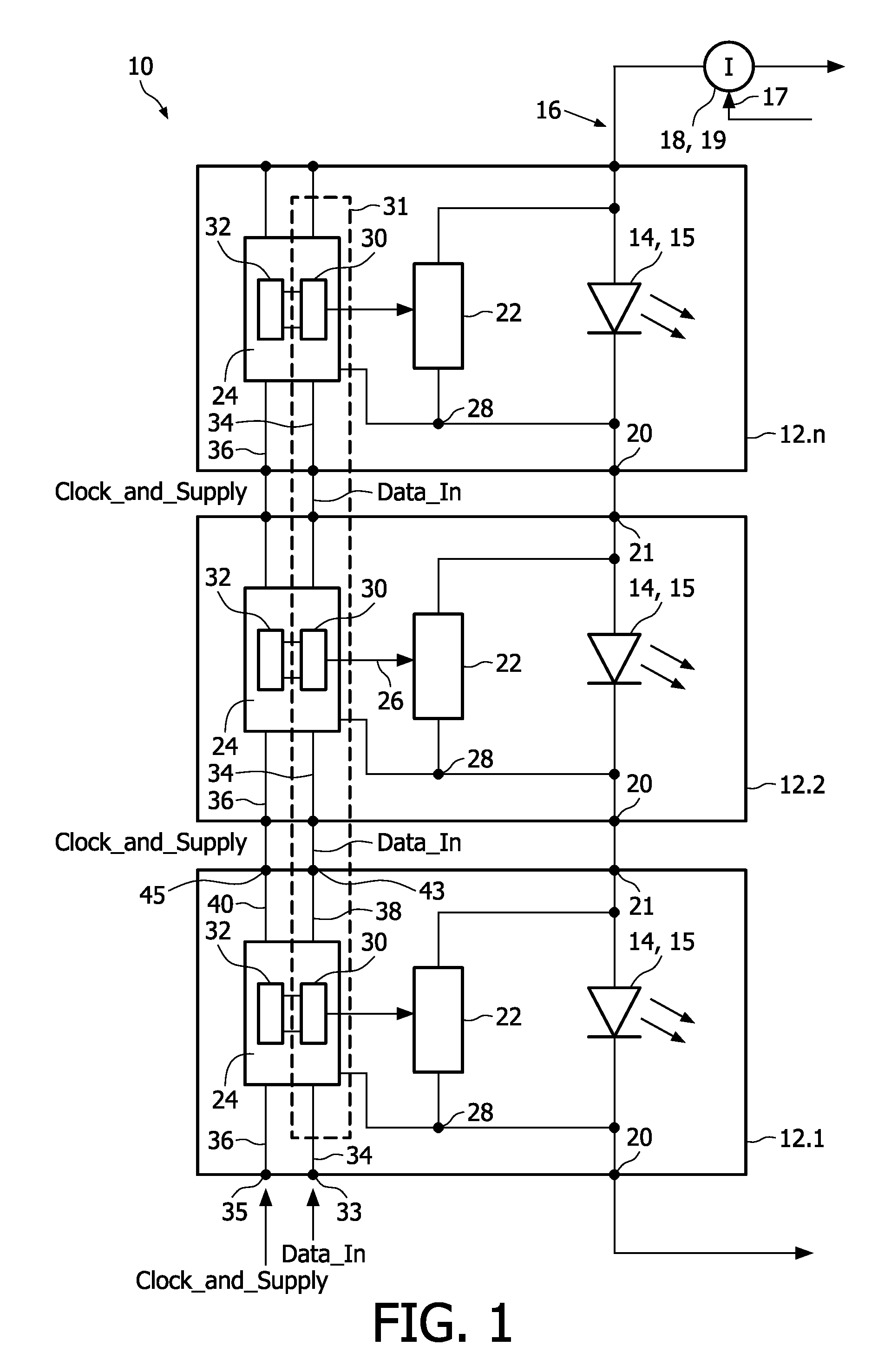
[0035]In FIG. 1, a driver device is schematically shown and indicated by means of reference numeral 10. The driver device 10 may be used for general illumination lamps with an enhanced control possibility or for pixelated lamps or to support spatial dimming or local highlighting in backlight and signage applications.

[0036]In particular, the driver device 10 is used in the shown embodiment to control light elements 14 which are coupled in series to form a string 16. The light elements 14 are provided as light emitting diodes 15 or organic light emitting diodes (OLED). Further, it is to be noted that each light element 14 may comprise one or more LEDs or OLEDs arranged in series, in parallel or a combination thereof. In the context of the following description, the expression LED 15 means generally a light element 14 of the afore-mentioned kind.

[0037]The LEDs 15 of the string 16 are powered by a power supply 18, which is for example a current source 19. The current source may be contr...


PUM


Abstract

The present invention relates to a device for individually driving OLED/LED elements of an OLED/LED string, comprising for each OLED/LED element of the string: a controllable shunting switch (22, 42) coupled with the respective OLED/LED element (14, 15), switch controller means (30, 44) for controlling said shunting switch (22, 42) and having a control output port coupled to said switch (22, 42), a data input port and a clock input port, level shifting means (32) assigned to said switch controller means (30, 44) and adapted to bring the control input data to a level sufficient to be accepted by the switch controller means (30, 44) during a programming mode and to allow the control of said shunting switch (22, 42). Said switch controller means (30, 44) of said OLED/LED elements (14, 15) are provided to form a serial-to-parallel converter means (31).

Description

FIELD OF THE INVENTION[0001]The present invention relates to a device for individually driving OLED / LED elements of an OLED / LED string. The invention also relates to a method of driving OLED / LED elements of an OLED / LED string individually.BACKGROUND OF THE INVENTION[0002]Lighting devices using LEDs or OLEDs (Organic Light Emitting Diode) gain more and more interest for general lighting applications. LEDs and OLEDs can be used to produce large amounts of light and have the benefit that they allow fast switching. On the one hand they can be used as general light sources, on the other hand they can be used as displays or design elements. In order to control the LEDs / OLEDs in a lighting device, so-called driver devices are used. In the art, there are a couple of solutions with respect to how to design such driver devices. For example, US 2006 / 0038803 A1 or WO 2006 / 107199 A2 disclose approaches regarding how to control LEDs coupled in series to form an LED string.[0003]Generally, using a...

Claims


Application Information

Patent Timeline
IPC IPC(8): H05B41/36H05B44/00
CPCH05B33/083H05B37/0254H05B33/0896H05B45/48H05B45/60H05B47/18Y02B20/30
Inventor RADERMACHER, HARALD JOSEF GUENTHERWENDT, MATTHIAS
Owner SIGNIFY HLDG BV
Why Eureka
Try Eureka