Power storage unit and vehicle having power storage unit
- Summary
- Abstract
- Description
- Claims
- Application Information
AI Technical Summary
Benefits of technology
Problems solved by technology
Method used
Image
Examples
first example embodiment
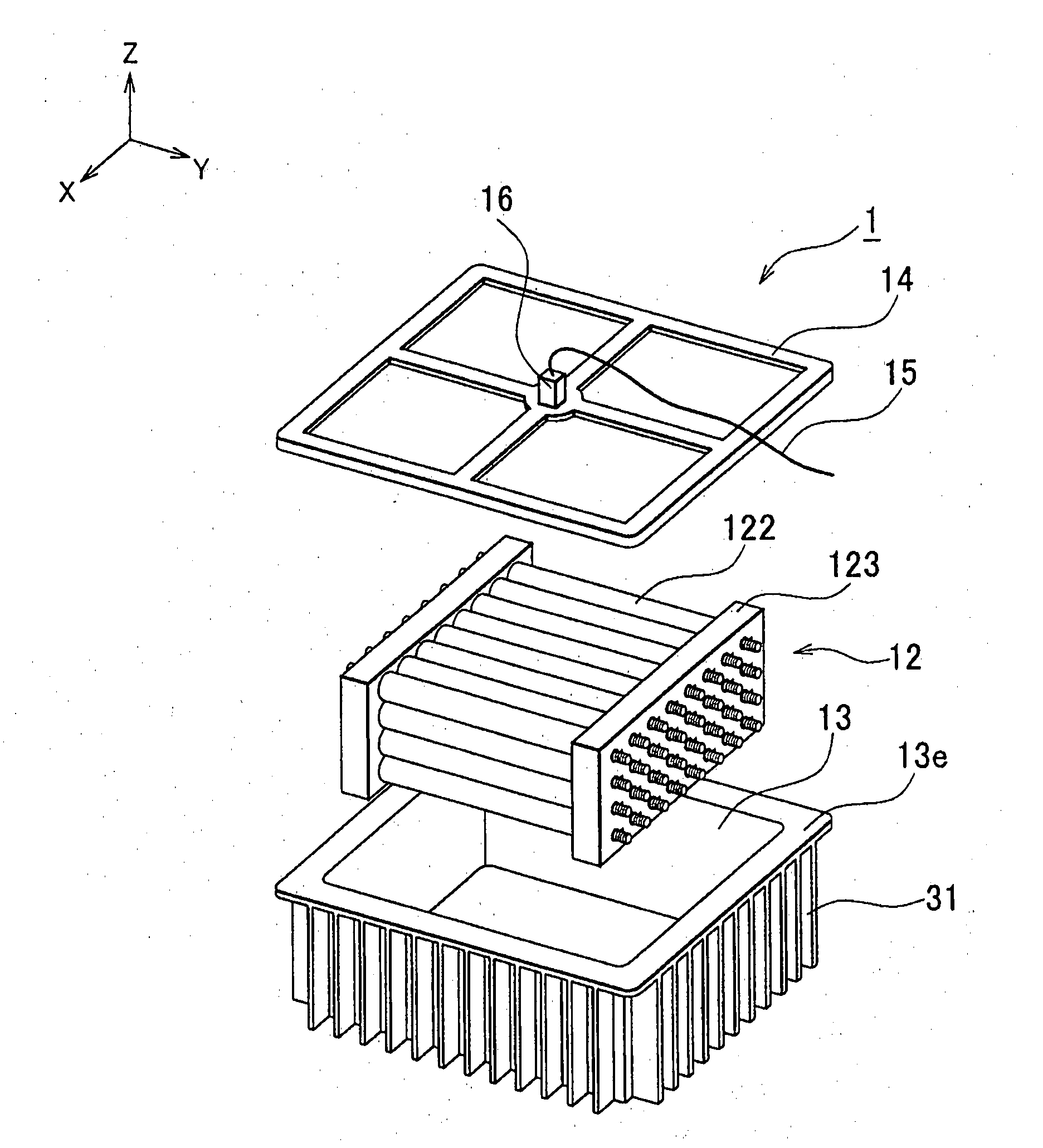
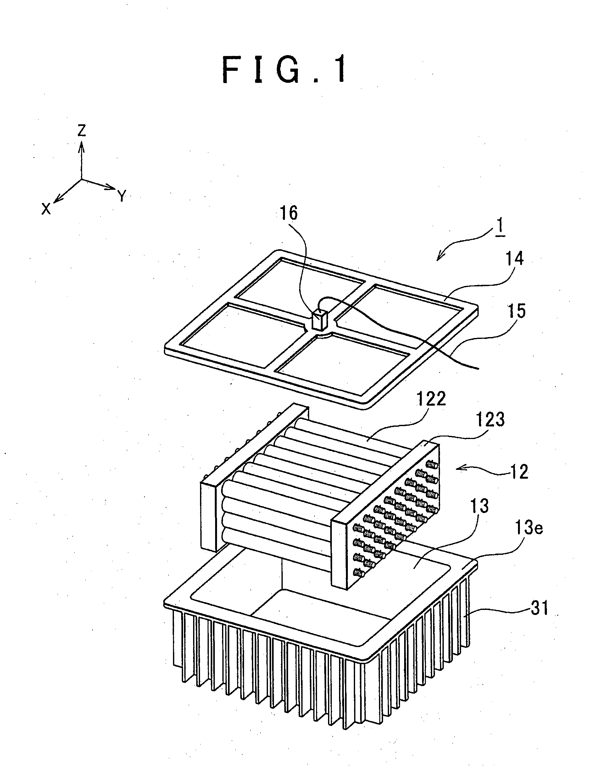
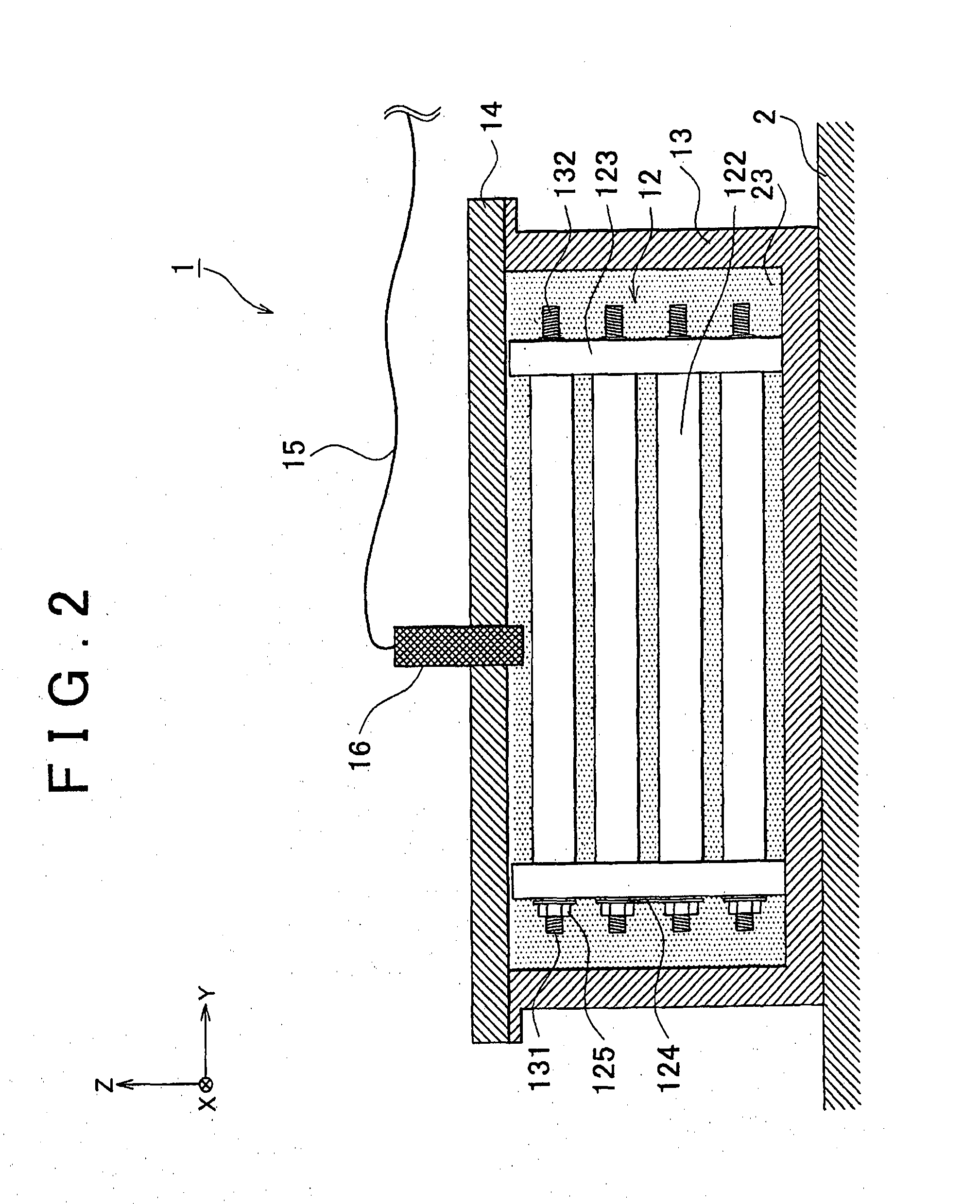
[0029]FIG. 1 is an exploded perspective view of a power storage unit 1 according to the example embodiment of the invention, and FIG. 2 is a cross-sectional view of the power storage unit 1. Hereinafter, the outline of the power storage unit 1 will be described with reference to FIG. 1 and FIG. 2.
[0030]The power storage unit 1 is used as a drive power source or an auxiliary power source for an electric vehicle or a hybrid vehicle and it is mounted on a floor panel 2 beneath the passenger's seat.
[0031]A battery assembly 12 and coolant 23 for cooling the battery assembly 12 are provided in a battery case 13, and an electric resistivity detector 16 is attached on a case lid 14 of the battery case 13 to detect the electric resistivity of the coolant 23. The invention is not limited in the case detecting the resistivity, it can detect the resistance of the coolant 23 instead. Note that the battery case 13 and the case lid 14 correspond to “casing” in the invention, the battery assembly 1...
second example embodiment
[0053]Next, the second example embodiment of the invention will be described with reference to FIG. 6 and FIG. 7. FIG. 6 is a block diagram showing the configuration of the circuit for preventing short circuits at the battery assembly 12. In FIG. 6, the dotted lines represent the electric connections, and the arrows represent the signal directions. FIG. 7 is a flowchart illustrating the procedure of a method for preventing short circuits at the battery assembly 12.
[0054]In the first example embodiment, as described above, the battery ECU 51 interrupts the output current of the battery assembly 12 in response to a decrease in the electric resistivity of the coolant 23. Meanwhile, in the second example embodiment, the battery ECU 51 first warns the passenger using an alarm lamp 53 and then interrupts the output current of the battery assembly 12 in response to a decrease in the electric resistivity of the coolant 23. Note that the structural elements other than the alarm lamp 53 in th...
third example embodiment
[0059]Next, the third example embodiment of the invention will be described with reference to FIG. 8. FIG. 8 is a flowchart illustrating the procedure of a method for preventing short circuits in the battery assembly 12.
[0060]In the first example embodiment, the battery ECU 51 interrupts the output current of the battery assembly 12 in response to a decrease in the electric resistivity of the coolant 23. Meanwhile, in the third example embodiment, the battery ECU 51 first raises a target power storage amount SOC and then interrupts the output current of the battery assembly 12 in response to a decrease in the electric resistivity of the coolant 23. Note that the structural elements are identical to those in the first example embodiment and therefore they are not described here again.
[0061]The battery ECU 51 continuously measures the electric resistivity of the coolant 23 that is output from the electric resistivity detector 16 (step S301). The battery ECU 51 determines whether the e...
PUM
 Abstract
Description
Claims
Application Information
 - R&D Engineer
- R&D Manager
- IP Professional
- Industry Leading Data Capabilities
- Powerful AI technology
- Patent DNA Extraction
Browse by: Latest US Patents, China's latest patents, Technical Efficacy Thesaurus, Application Domain, Technology Topic, Popular Technical Reports.
© 2024 PatSnap. All rights reserved.Legal|Privacy policy|Modern Slavery Act Transparency Statement|Sitemap|About US| Contact US: help@patsnap.com


