Rapid exchange battery construction

Active Publication Date: 2010-06-03
IND TECH RES INST
View PDF5 Cites 71 Cited by
  • Summary
  • Abstract
  • Description
  • Claims
  • Application Information

AI Technical Summary

Benefits of technology

[0009]The conventional battery fixing mechanism may be disassembled and assembled rapidly by employing a simple structure design, but a separation tends to occur in an unexpected case. When employing a complicated structural design, an electrical connection relationship of the electrodes may be ensured, but a complicated structure increases the production cost, and

Problems solved by technology

The conventional battery fixing mechanism may be disassembled and assembled rapidly by employing a simple structure design, but a separation tends to occur in an unexpected case.
When employing a complicated structural design, an electrical connection relationship of the electrodes may be ensured, but a complicated st

Method used


Image

  • Rapid exchange battery construction
  • Rapid exchange battery construction
  • Rapid exchange battery construction

Examples


first embodiment

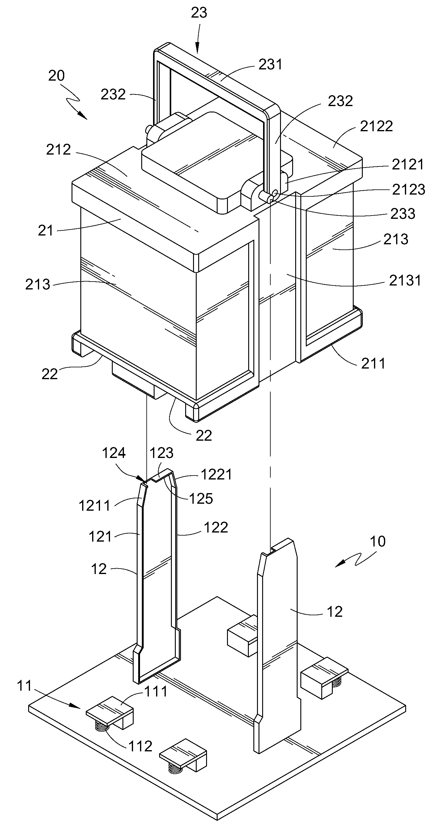
[0021]Referring to FIG. 1, the present invention is shown. In the rapid exchange battery construction disclosed according to the present invention, a battery assembly structure includes a base 10 and a battery module 20.

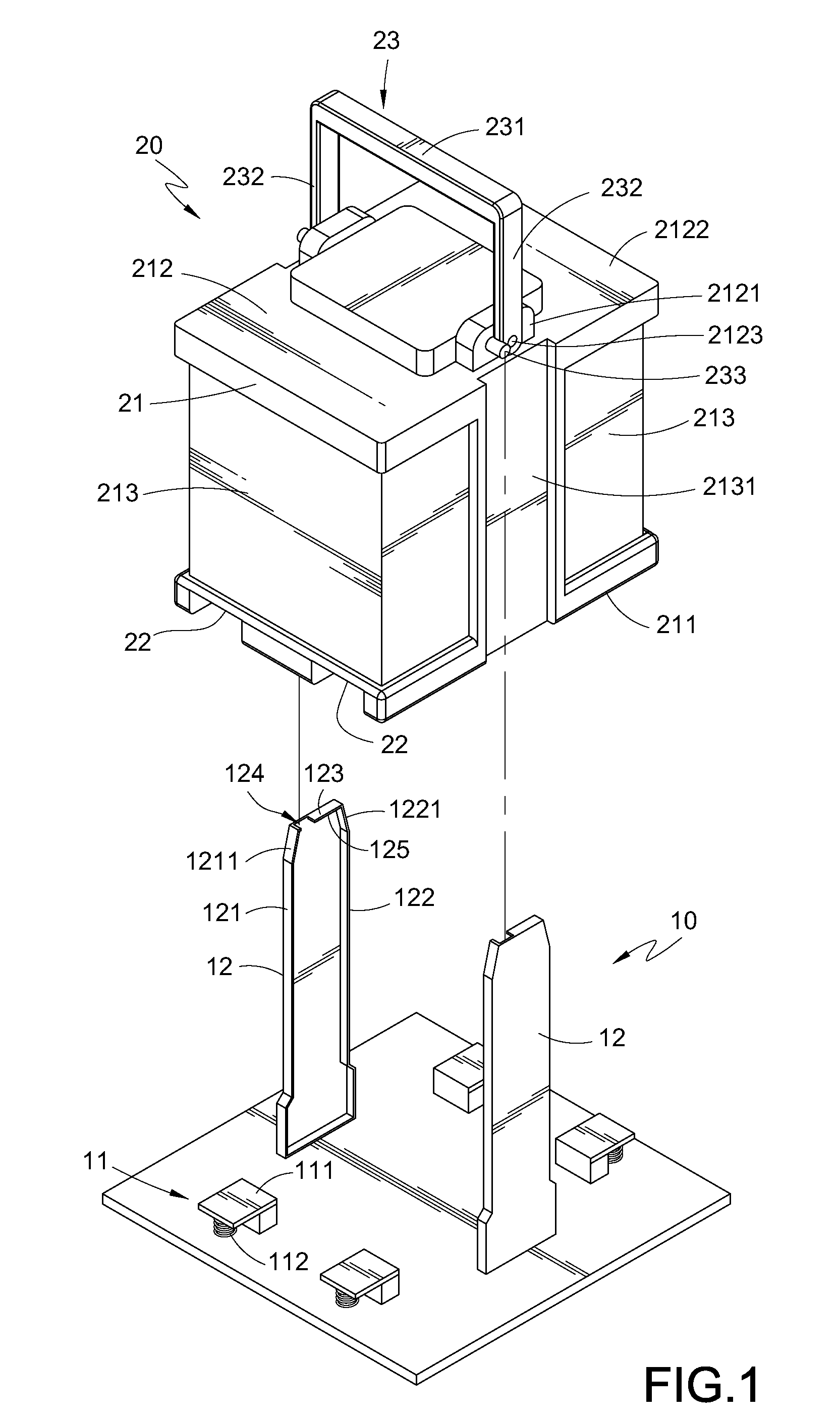
[0022]The base 10 is disposed in a battery reception space (not shown) of the electric motorcycle, and a plurality of electrode terminals 11 is provided on the base 10. Referring to FIG. 2 in combination, a motor of the electric motorcycle is electronically connected to the electrode terminals 11 via a lead 30. The electrode terminal 11 includes a conducting strip 111 and an elastic element 112 disposed under the conducting strip 111. The elastic element 112 may be a spring or an elastic rubber, so as to provide an elastic force for compressing or resetting the conducting strip 111.

[0023]A pair of fixing structures 12 (columns as shown) are erected on the base 10, and the two fixing structures 12 are spaced apart by a distance to constitute a range for accommodating ...

second embodiment

[0031]Referring to FIG. 5, a rapid exchange battery construction according to the present invention is shown, in which the battery assembly structure includes a base 10a and a battery module 20a.

[0032]The base 10a is substantially the same as the base 10 of the first embodiment, except that the base 10a is a cabinet for directly placing the battery module 20a therein. The base 10a also has two fixing structures 12a, and a releasing opening 124a of the two fixing structures 12a is disposed between a top edge of a side wall 121a and a top wall 123a, i.e., at a side edge of the fixing structure 12a. An engaging block 126a is disposed on an inner face of the fixing structure 12a, and the engaging block 126a assumes a semi-circular body with the arc face downwards.

[0033]The battery module 20a is substantially the same as the battery module 20 of the first embodiment, except that the battery module 20a may be directly placed into the base 10a, i.e., the guiding slot 2131 of the first emb...


PUM


Abstract

A rapid exchange battery construction is applied in a battery module of an electric device to supply power. The battery module is pivoted with a rotatable handle, a catching member is disposed on the handle, and a fixing structure is erected on a base of a battery assembly structure. A pressing portion and a releasing opening are disposed at a top edge of the fixing structure. The handle is rotated to a gripping position for lifting the battery module to install the battery module on the base along the fixing structure, and then, the handle is rotated to a withdrawal position to move the catching member to the pressing portion. The battery structure is designed in such a manner that the battery module is secured and fixed on the base, and an electrical connection relationship between the battery module and the electric device is ensured.

Description

CROSS-REFERENCE TO RELATED APPLICATIONS[0001]This non-provisional application claims priority under 35 U.S.C. §119(a) on Patent Application No(s). 097147022 filed in Taiwan, R.O.C. on Dec. 3, 2008 the entire contents of which are hereby incorporated by reference.BACKGROUND OF THE INVENTION[0002]1. Field of Invention[0003]The present invention relates to a battery module construction, and more particularly to an exchange battery construction capable of being disassembled and assembled rapidly.[0004]2. Related Art[0005]Environment protection is a very important topic in the human society, and the exhaust emission of traditional oil-fired vehicles is the largest mobile pollution source, while the exhaust pollution would be efficiently reduced by employing a hybrid electric vehicle or an electric vehicle, such as an electric motorcycle or an electric bicycle.[0006]The electric vehicle supplies power completely through a battery, which is a very important key component. In order to maint...

Claims


Application Information

Patent Timeline
IPC IPC(8): H01M2/10H01M50/244H01M50/262H01M50/296
CPCB60L11/007B60L11/1822B60L11/1879B60L2200/12H01M2/1005Y02T90/14Y02T10/7005Y02T10/705Y02T10/7072Y02T90/124H01M2/1083B60L50/20B60L53/80B60L50/64Y02T10/70Y02E60/10H01M50/256H01M50/296H01M50/244H01M50/262Y02T90/12
Inventor GAU, TIEN-HOPENG, YU-YIN
Owner IND TECH RES INST
Why Eureka
Try Eureka