Medical implantable lead

Inactive Publication Date: 2010-06-03
ST JUDE MEDICAL
View PDF7 Cites 23 Cited by
  • Summary
  • Abstract
  • Description
  • Claims
  • Application Information

AI Technical Summary

Benefits of technology

[0008]Providing the header with a pocket and putting the marker ring therein is a simple solution of mounting the radiopaque ring in a shielded way, and an end portion of the helical fixation element is invisible on fluoroscopy when being inside of the ring, until it is extended from the header. Alternatively, or additionally, the radiopaque ring is used as a position reference in cooperation with a proximal radiopaque movable part, which follows the helix when the helix is extended or retracted. Further, the radiopaque ring is mountable from the proximal end of the header by simply moving it distally along the first tubular portion and into the pocket.
[0010]In accordance with an embodiment of the medical implantable lead, it further has a ring electrode, which is arranged at the header and connected to a conductor. The conductor extends between the ring electrode and the proximal end of the lead. The ring electrode is arranged adjacent to the radiopaque ring, and has the same outer diameter as the second tubular portion. Thereby the ring electrode as well as the radiopaque ring is easily mountable onto the header.
[0011]In accordance with an embodiment of the medical implantable lead, the ring electrode and the radiopaque ring are welded together. Thereby the mounting is further facilitated and shatter-noise, due to the rings having irregular contact with each other, is avoided.
[0015]In accordance with an embodiment of the medical implantable lead, a distal end surface of the header is textured such as to obtain an increased friction towards a biological tissue relative to a smooth surface. This embodiment is, inter alia, advantageous in that it reduces the risk of the header rotation along with the helical fixation element when it is to be extended by rotation thereof. In another embodiment of the lead according to the present invention, the texture is chosen such as to generate an enhanced response from the body tissue, which is engaged with the surface.

Problems solved by technology

Then it will not be possible to weld the header with the radiopaque ring, but it will be necessary to use an adhesive.

Method used


Image

  • Medical implantable lead
  • Medical implantable lead

Examples


Embodiment Construction

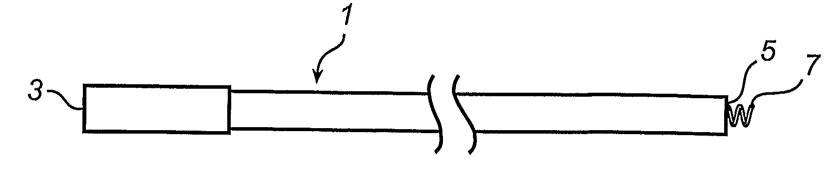
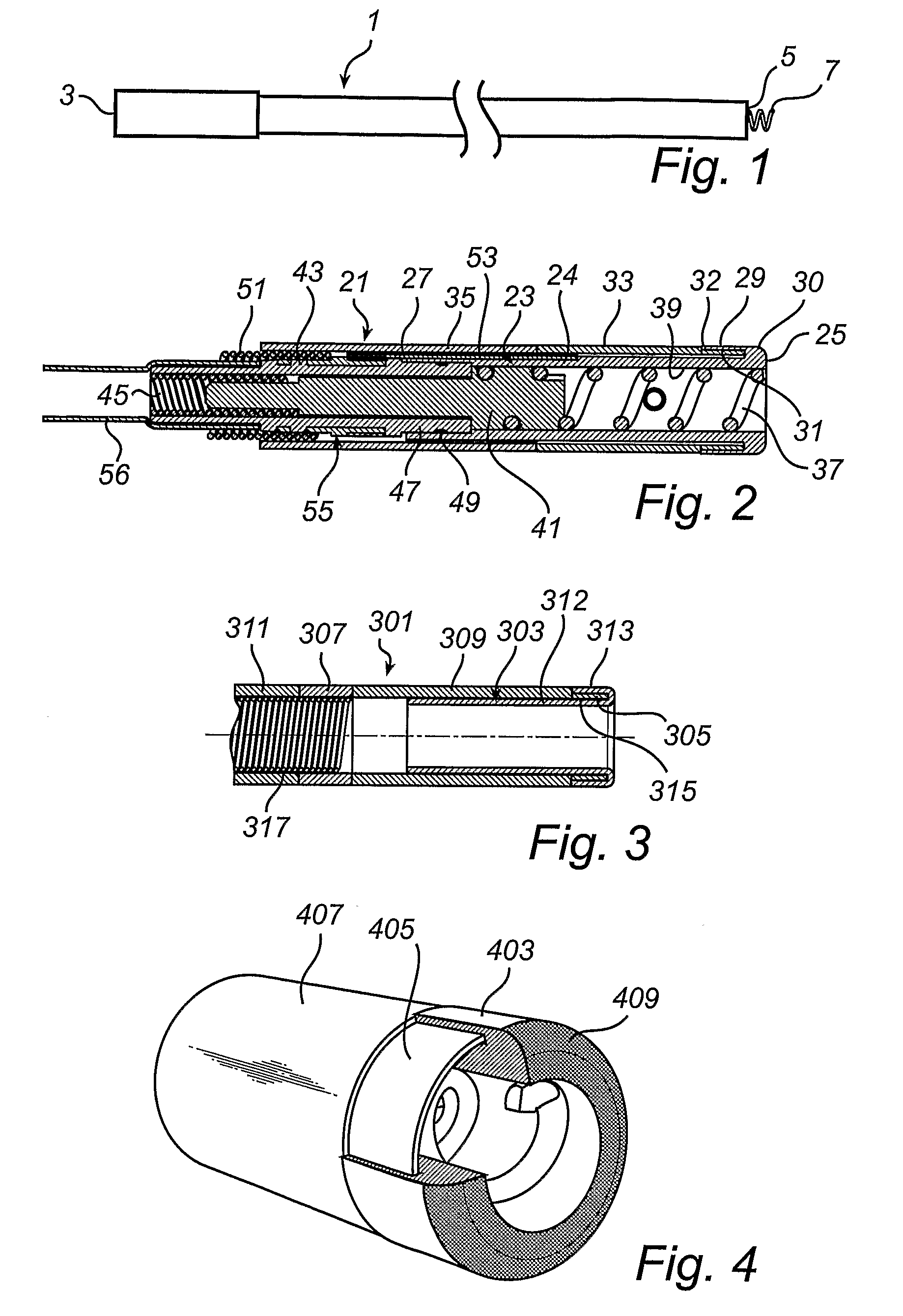
[0020]Referring to FIG. 1 a medical implantable lead 1 has a proximal end 3 and a distal end 5. At the distal end 5 a helical fixation element 7 is arranged within a lumen 39, see FIG. 2, of the lead 1. The helical fixation element, which below will be referred to as a helix, 7 is extendable from the distal end 5, and retractable into the lumen. In FIG. 1 it is shown in the extended position. The lead shown in FIG. 1 is most schematic but also general figure of a lead. Thus, the description thereof is valid for all embodiments that will be described below. For example the lead 1 is used with a pulse generator, where the distal end 5 thereof is introduced into a cardiac cavity.

[0021]In accordance with a first embodiment of the lead according to the present invention, as shown in FIG. 2, a distal end assembly of the lead 21 comprises a header 23, a radiopaque ring, or marker ring, 31, ring electrode 33, a helix 37, and a shaft 41. The header 23 has a proximal end 27 and a distal end 2...


PUM


Abstract

A medical implantable lead has a proximal end and a distal end, a biostable and biocompatible polymeric header, which is arranged at the distal end and has a first tubular portion, a helical fixation element located within the first tubular portion and being extendable from a distal end of the header, and a radiopaque ring. The header further has a second tubular portion, which is arranged coaxially of the first tubular portion and is attached to the first tubular portion at a distal end of the second tubular portion, while having a free proximal end. The tubular portions form a circumferential pocket, wherein the first tubular portion extends from the proximal end of the header at least to said distal end of the second tubular portion. The radiopaque ring is arranged around the first tubular portion and is received in the circumferential pocket.

Description

BACKGROUND OF THE INVENTION[0001]1. Field of the Invention[0002]The present invention relates to a medical implantable lead having a header arranged at a distal end thereof and a radiopaque ring arranged at the header.[0003]2. Description of the Prior Art[0004]A lead of the type mentioned above typically has a lumen extending between its ends and an electrode extending through the lumen. In order to be able to securely connect the electrode to body tissue a helical fixation element, also called helix, is arranged at the distal end of the electrode. The helix is extendable and retractable within the lumen by means of rotating the helix. The tip of the helix is sharp in order to easily penetrate body tissue. In order to be able to provide good guidance to a user who is going to fasten the helix in the body tissue, a radiopaque ring is applied as close to the distal end of the header as possible. The ring is used as a marker, or position reference, for the position of the helix.[0005]O...

Claims


Application Information

Patent Timeline
IPC IPC(8): A61N1/05
CPCA61N1/0573A61N1/0565
Inventor ECKERDAL, JOHAN
Owner ST JUDE MEDICAL
Why Eureka
Try Eureka