Friction drive vehicle

a technology of friction drive and drive roller, which is applied in the direction of friction roller based transmission, cycles, transportation and packaging, etc., can solve the problems of affecting the power transmission efficiency, and affecting the bearings of the drive roller and the driven roller

Active Publication Date: 2010-06-10
HONDA MOTOR CO LTD
View PDF8 Cites 26 Cited by
  • Summary
  • Abstract
  • Description
  • Claims
  • Application Information

AI Technical Summary

Benefits of technology

[0006]In view of such problems of the prior art and the recognition by the inventors, a primary object of the present invention is to provide a frictional drive vehicle that can achieve an optimum contact pressure between a drive roller and a driven roller under all load conditions.

Problems solved by technology

If the contact pressure is too small, a slippage arises between the drive roller and driven roller, and this impairs the power transmission efficiency.
If the contact pressure is too great, the frictional resistance produced between the drive roller and driven roller becomes excessive, and this also impairs the power transmission efficiency.
Additionally, an excessive contact pressure adversely affects the bearings for the drive roller and driven roller.

Method used


Image

  • Friction drive vehicle
  • Friction drive vehicle
  • Friction drive vehicle

Examples


Embodiment Construction

)

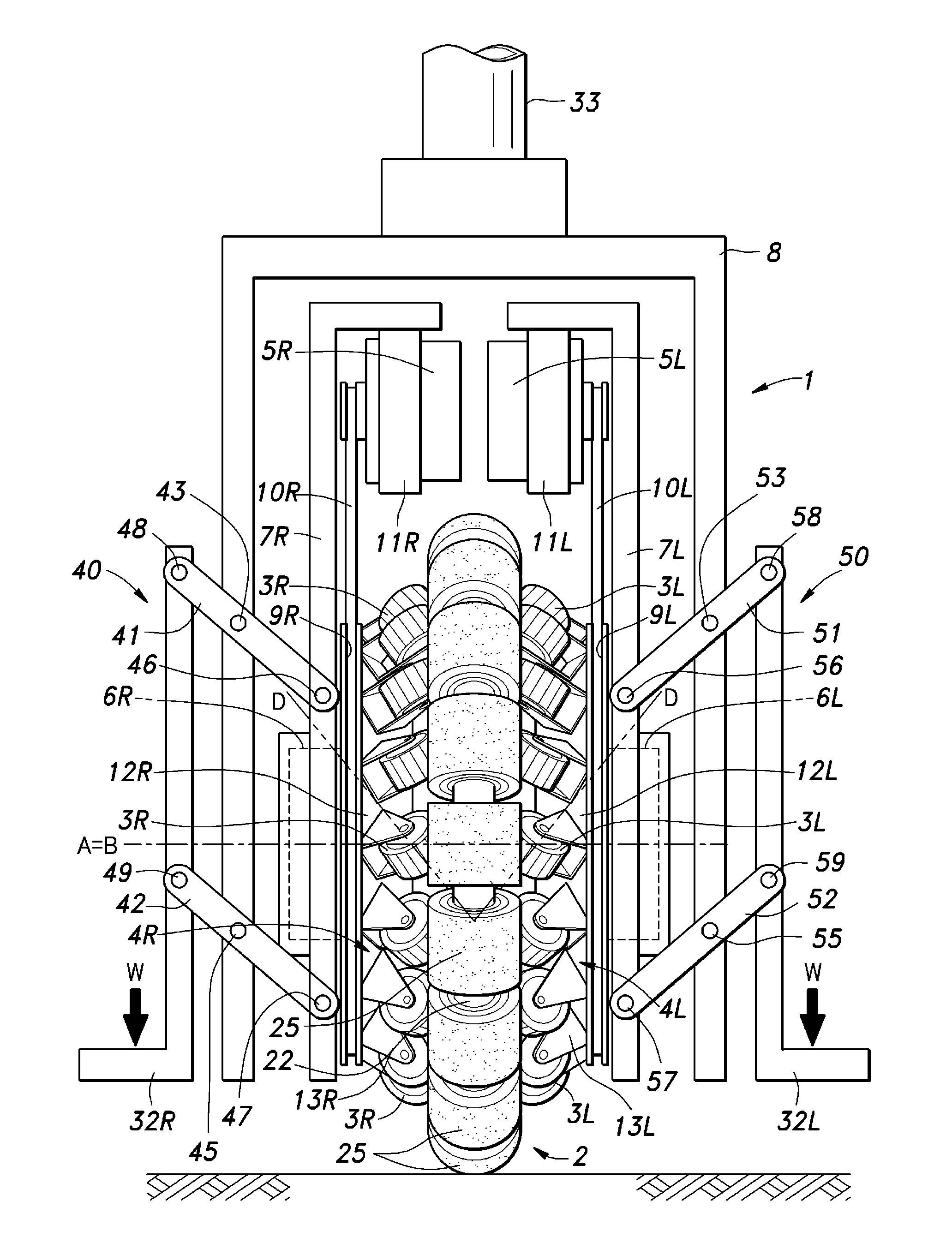
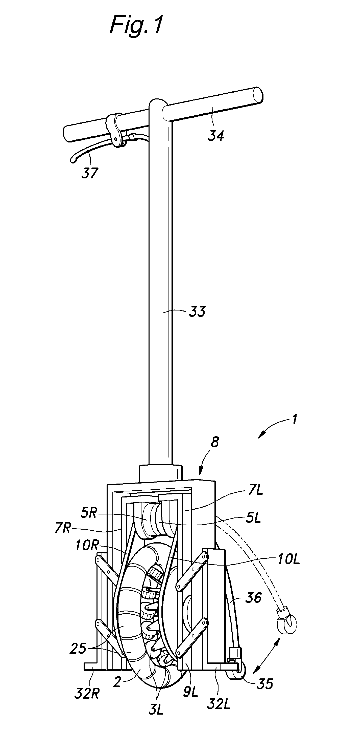
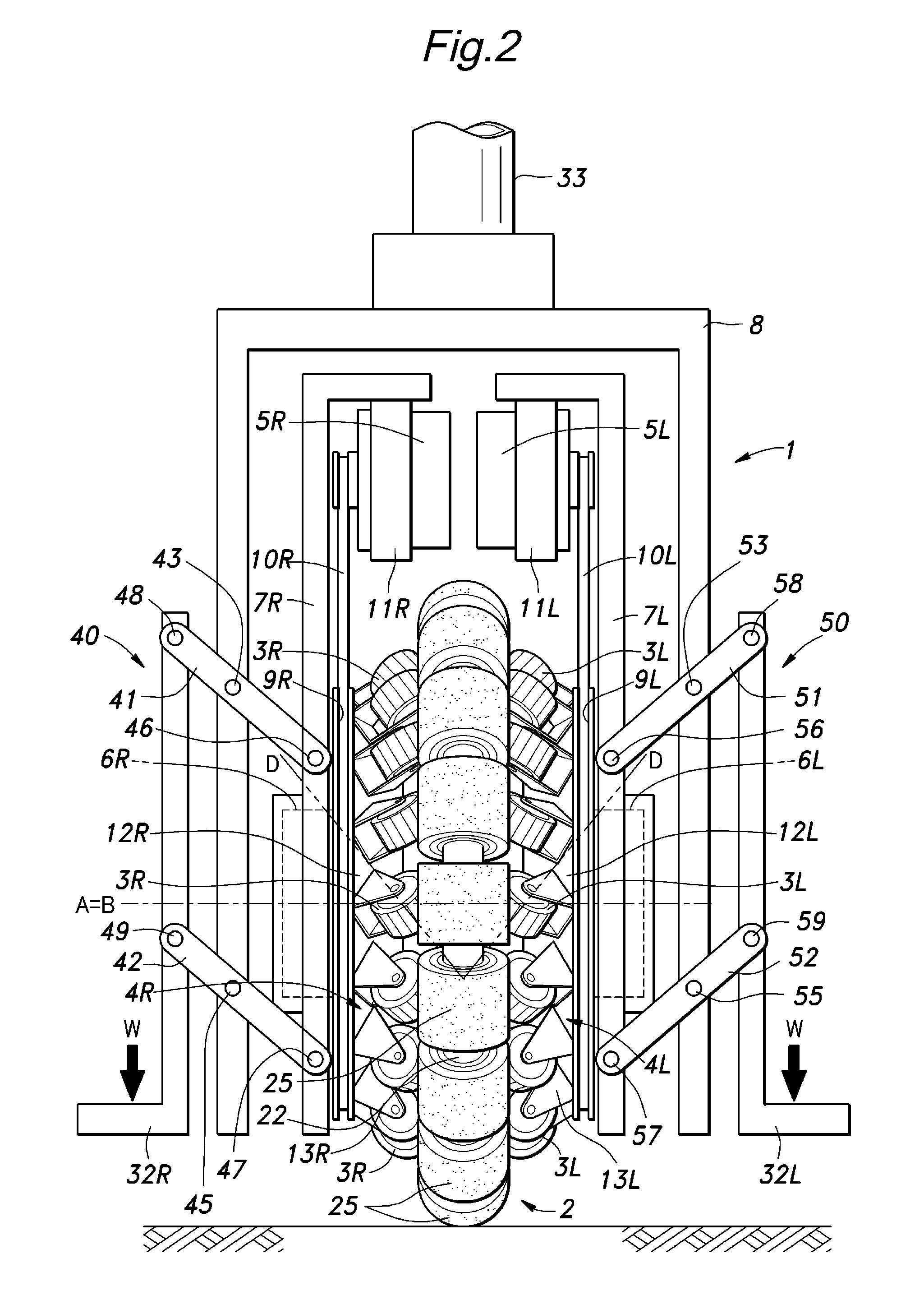
[0016]Referring to FIGS. 1 to 3, an omni-directional vehicle 1 embodying the present invention is described in the following.

[0017]The omni-directional vehicle 1 of the illustrated embodiment comprises a vehicle body 8 including a pair of leg members disposed on either side and a cross member joining the upper ends of the leg members to each other. A pole 33 extends vertically upward from a middle part of the cross member and a laterally extending handle bar 34 is attached to the upper end of the pole 33.

[0018]A pair of vertical frame members consisting of a right frame member 7R and left frame member 7L are disposed inside the vehicle body 8 so as to extend in parallel with the corresponding leg members of the vehicle body 8, and are each supported by the corresponding leg member of the vehicle body 8 via a four-link parallel link mechanism 40, 50.

[0019]The right four-link parallel link mechanism 40 comprises an upper and lower link 41 and 42 having an equal length, and extending ...


PUM

PropertyMeasurementUnit
electric poweraaaaaaaaaa
forceaaaaaaaaaa
rotational movementsaaaaaaaaaa

Abstract

In a frictional drive vehicle, a load acting on the vehicle such as the weight of a rider is converted into a force that urges two frictionally engaging parts (3L, 3R, 25) toward each other. Thereby, the contact pressure between the two frictionally engaging parts is maintained at an optimum level under all conditions. A weight of a rider may be transmitted to a drive member that frictionally engages a main wheel via a four-link parallel link mechanism (40, 50).

Description

TECHNICAL FIELD[0001]The present invention relates to a friction drive vehicle, and in particular to a friction drive vehicle suitable for use as an omni-directional vehicle that can travel in any desired direction in a two dimensional environment.BACKGROUND OF THE INVENTION[0002]A drive device for an omni-directional vehicle that can freely move about on a floor is known, for instance, from Japanese patent No. 3820239 (patent document 1). In particular, reference should be made to the third embodiment illustrated in FIGS. 17 and 18 of this patent document. The illustrated drive device includes a rotatively driven wheel and a plurality of shafts attached to the outer periphery of the driven wheel and each extending in a tangential direction. A barrel shaped roller divided into a plurality of parts is supported by each shaft so as to be rotatable around the shaft, and each barrel shaped roller is engaged to the adjacent rollers so as to transmit the rotational movements of the barrel...

Claims


Application Information

Patent Timeline
Patent Type & Authority Applications(United States)
IPC IPC(8): B60K17/30B60B19/12
CPCB60B19/003B62D61/00B60B19/14B60B2200/47B60B2360/10B60B2360/32B60B2360/324B60B2360/50B60K17/043B60K17/30B60Y2200/81B62K1/00B62K3/002B62K2204/00B62K3/007B60B19/125B62K11/007
Inventor TAKENAKA, TORUHIRANO, MAKOTOIZUMI, HIDEHARUKUWABARA, KAZUYAKOYAMA, TAIJISASAKI, MASAOGOMI, HIROSHIKOBASHI, SHINICHIRO
Owner HONDA MOTOR CO LTD
Why Eureka
Try Eureka