Lifting device

a technology of lifting device and lifting plate, which is applied in the direction of lifting device, etc., can solve the problem that the lifting plate used for this purpose must have a small installation size, and achieve the effect of high torque and lifting very large loads

Inactive Publication Date: 2010-06-10
GKSS FORSCHUNGSZENTRUM GEESTHACHT GMBH
View PDF20 Cites 9 Cited by
  • Summary
  • Abstract
  • Description
  • Claims
  • Application Information

AI Technical Summary

Benefits of technology

[0011]The achievement of the dome being located in the interior of the lifting spindle is that with a large total travel, a more compact design is nevertheless possible compared to the prior art as it is no longer necessary to have additional guide elements located in the axial direction in front of and behind the lifting spindle, rather these are provided in the interior of the hollow-cylindrical lifting spindle.
[0012]In a preferred embodiment, the drive unit has, on the one hand, a worm gear mounted on the threaded bush and, on the other hand, a worm shaft that is in engagement with said worm gear and in turn is driven in a rotating manner. This type of design makes it possible for a comparatively high torque to be exerted onto the threaded bush such that the lifting device is capable of lifting very large loads.

Problems solved by technology

If this type of lifting device is to be used to lift an object in a positionally precise manner within a room that has a predetermined ceiling height, the height of the object being the same size as the height of the room, the problem arises that a lifting device used for this purpose must have as small an installation size as possible in the axial length of the lifting spindle.

Method used


Image

  • Lifting device
  • Lifting device
  • Lifting device

Examples


Embodiment Construction

[0027]The present invention is susceptible of embodiment in many different forms. While the drawings illustrate, and the specification describes, certain preferred embodiments of the invention, it is to be understood that such disclosure is by way of example only. There is no intent to limit the principles of the present invention to the particular disclosed embodiments.

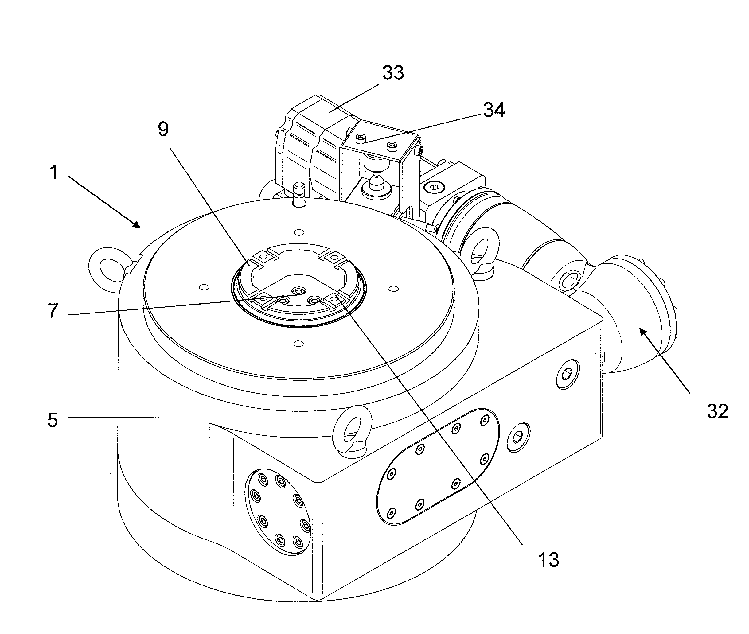
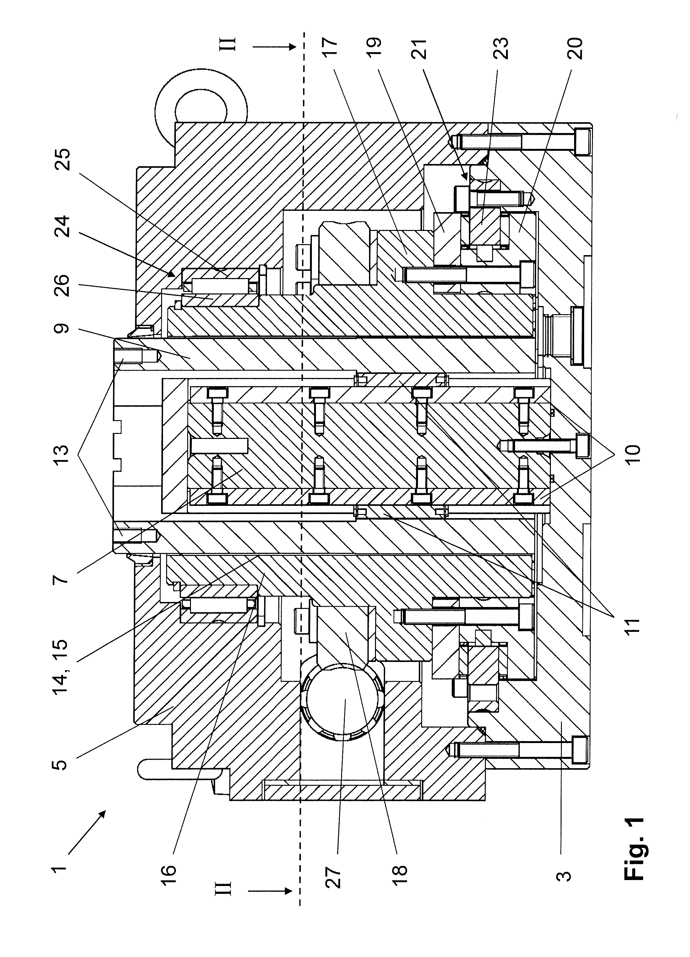
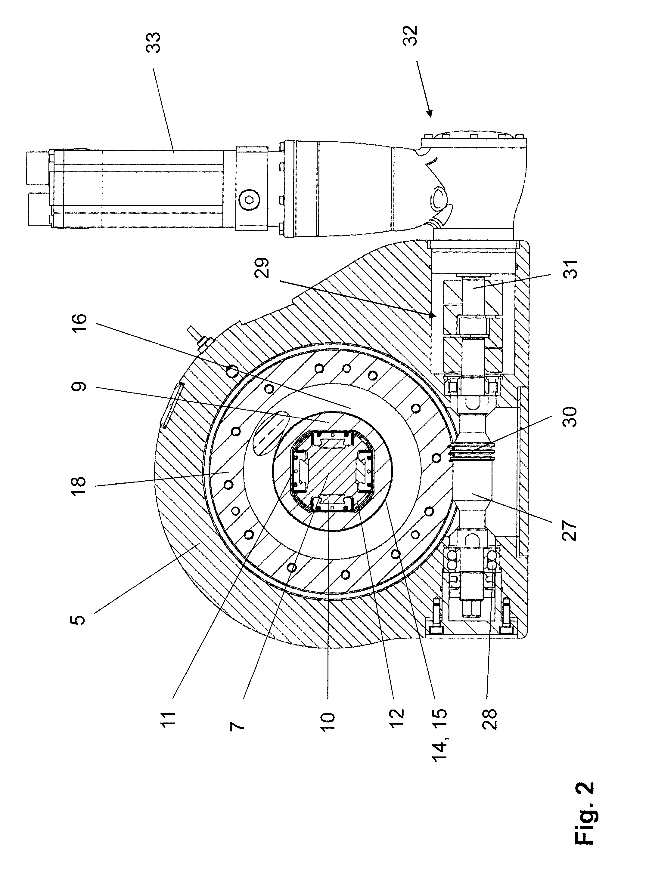
[0028]FIG. 1 represents an exemplary embodiment of a lifting device 1 according to the invention. The lifting device 1 has a base plate 3, which can rest on a surface area and to which a housing 5 and a dome 7, which extends vertically from the base plate 3, are screw-connected.

[0029]The dome 7 is surrounded by a lifting spindle 9 that is in the form of a hollow cylinder. A linear guide is provided on the dome 7, said linear guide including four guide rails 10 that are screw-connected to the dome 7, are distributed uniformly over the circumference of the dome 7 and extend in each case over the entire axial length of ...


PUM


Abstract

Represented and described is a lifting device having a housing, a lifting spindle that is cylindrical and has an external thread on the outer surface, a threaded bush that surrounds the lifting spindle and has an internal thread that is in engagement with the external thread and a drive unit for the rotating drive of the threaded bush, wherein the lifting spindle is mounted in the housing so as to be displaceable in its axial direction and non-rotatable. The object to provide a lifting device that has as short an installation length as possible in the axial direction of the lifting spindle is achieved in that the lifting spindle is in the form of a hollow cylinder, in that a dome is located in the interior of the lifting spindle and is connected in a non-rotatable manner to the housing and in that the lifting spindle is mounted on the dome so as to be non-rotatable and axially displaceable.

Description

CROSS-REFERENCE TO RELATED APPLICATION[0001]The present application claims the benefit of and priority from German Patent Application Serial No. DE 10 2008 062 317.2, filed Dec. 8, 2008, the entire disclosure of which is hereby incorporated by reference herein.BACKGROUND OF THE INVENTION[0002]1. Field of the Invention[0003]The present invention relates to a lifting device having a housing, a lifting spindle that is cylindrical and has an external thread on the outer surface, a threaded bush that surrounds the lifting spindle and has an internal thread that is in engagement with the external thread and a drive unit for the rotating drive of the threaded bush, wherein the lifting spindle is mounted in the housing so as to be displaceable in its axial direction and non-rotatable.[0004]2. Discussion of the Prior Art[0005]DE 29 20 133 B1 makes known a lifting device with two threaded spindles that are able to be moved in a telescopic manner towards one another, the outer threaded spindle...

Claims


Application Information

Patent Timeline
Patent Type & Authority Applications(United States)
IPC IPC(8): B66F3/16B66F3/18
CPCB66F3/18B66F3/08
Inventor SIEMERS, DIRK JANRUHNKE, BERNHARD
Owner GKSS FORSCHUNGSZENTRUM GEESTHACHT GMBH
Why Eureka
Try Eureka