Lathe fixture for clamping automobile hub

a technology for automobile hubs and lathes, applied in the field of automobile engineering, can solve the problems of increasing the labor intensity of workers, reducing production efficiency, increasing the time of workshop assistance, etc., and achieves the effect of reducing the overall weight of the lathe fixture, facilitating relaxation/clamping, and increasing rotation speed

Active Publication Date: 2020-01-07
CITIC DICASTAL
View PDF19 Cites 3 Cited by
  • Summary
  • Abstract
  • Description
  • Claims
  • Application Information

AI Technical Summary

Benefits of technology

[0004]The object of the present application is to provide an automobile hub lathe fixture, thereby achieving safe and effective clamping of an automobile hub.
[0016]Compared with the conventional automobile hub lathe fixture, the present application has a large relaxing / clamping travel and may adapt to the machining of hubs of multiple sizes.
[0017]The deflection block is adopted in the present application to counteract a part of centrifugal force of the clamping jaw, the positioning pull rod and other parts. The proportional range of the force arm of the deflection block of the present application is 1 to 5, which is greater than the proportion of the force arm of the conventional fixture. For generating the same centrifugal force resistance, the mass of the balance block used in the present application is much lower than that of the balance block adopted in the conventional fixture, which is advantageous for reducing the overall weight of the lathe fixture, so that the lathe fixture may work at a higher rotation speed and the work efficiency is improved.
[0018]The positioning pull rod of the present application has an integral structure and is directly connected and fixed to the power chuck by screws, which reduces the intermediate transmission link of the conventional fixture and enhances the service reliability of the lathe fixture.
[0019]The height of the positioning surface of the clamping jaw mounted on the positioning pull rod of the present application relative to the power chuck is greatly reduced over the conventional fixture, thereby reducing the influence of the bending moment on the positioning pull rod and prolonging the service life of the positioning pull rod.
[0020]The support shaft of the present application is connected and fixed between the circular plate and the second base, and shares the bearing weight of the first base of the forged aluminum alloy to the overall lathe fixture, thereby enhancing the overall rigidity of the lathe fixture.

Problems solved by technology

If wheels of another size are to be machined, a few groups of positioning and clamping mechanisms need to be replaced, which increases the production assistance time of the workshop, reduces the production efficiency and increases the labor intensity of workers.
In addition, the existing first-step fixture and second-step fixture adopt too heavy balance blocks for balancing the centrifugal force of fixture rotating bodies.
If the rotating speed of a machine tool spindle is to be improved to increase the production efficiency, upper structure of the fixture will bear a large centrifugal force, which is even beyond safe use condition of the fixture.

Method used


Image

  • Lathe fixture for clamping automobile hub
  • Lathe fixture for clamping automobile hub
  • Lathe fixture for clamping automobile hub

Examples


Embodiment Construction

[0027]The specific embodiments of the present application will be further described in detail below in combination with the accompanying drawings.

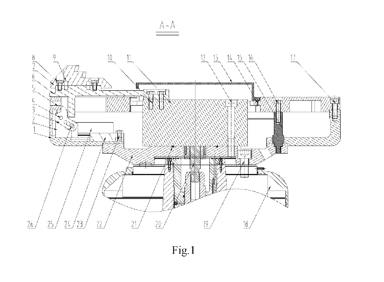
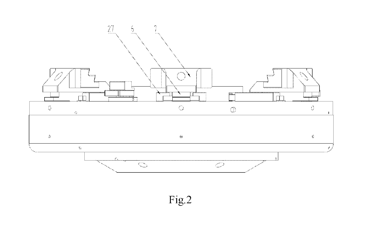
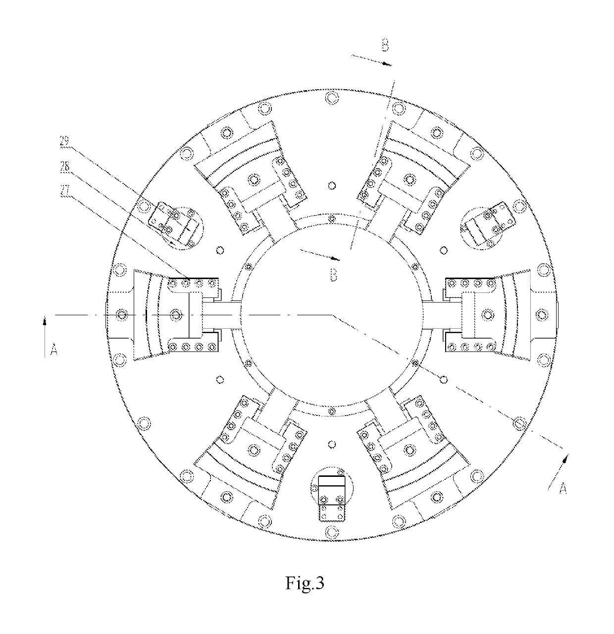
[0028]A lathe fixture for clamping an automobile hub, including a first base 1, a deflection block support block 2, a deflection block 3, a deflection block guide shaft 4, a circular plate 5, a positioning pull rod 6, a clamping jaw 7, first screws 8, first pins 9, second screws 10, a power chuck 11, third screws 12, a dust cover 13, fourth screws 14, a support shaft 15, a fifth screw 16, sixth screws 17, a spindle body 18, seventh screws 19, a rivet 20, an O-shaped rubber ring 21, a second base 22, eighth screws 23, a balance block guide rail 24, a balance block 25, a balance block guide shaft 26, a positioning pull rod pressure plate 27, an airtight base 28, an airtight lifting plate 29 and second pin 30, the second base 22 is connected with the first base 1 via a group of eighth screws 23 and the second pin 30, the circular plate 5 is c...


PUM

PropertyMeasurementUnit
angleaaaaaaaaaa
angleaaaaaaaaaa
angleaaaaaaaaaa

Abstract

The present application provides a lathe fixture for clamping an automobile hub, including a first base, a deflection block support block, a deflection block, a deflection block guide shaft, a circular plate and the like, a second base is connected with the first base via a group of eighth screws and a second pin, the circular plate is connected with the first base via a group of sixth screws, a power chuck is connected to the second base via a group of third screws, and an O-shaped rubber ring is placed between a power chuck and a groove of the second base. Compared with the conventional automobile hub lathe fixture, the lathe fixture has a large relaxing / clamping travel and may adapt to the machining of hubs of multiple sizes.

Description

CROSS-REFERENCE TO RELATED APPLICATIONS[0001]This application claims priority to Chinese Patent Application No. 201711235363.3 filed on Nov. 30, 2017, which is hereby incorporated by reference in its entirety.TECHNICAL FIELD[0002]The present application relates to the field of automobile engineering, specifically to an automobile hub lathe fixture.BACKGROUND ART[0003]A plurality of processes including machining, airtightness detection, spraying and the like are needed from a wheel blank to an available finished product. In the machining process, the wheel blank is usually machined in three steps. The existing first-step fixture, second-step fixture and three-step fixture are not the same in structure, but they have a common feature that the fixtures may only be applied to wheels of a fixed size compatible with their sizes. If wheels of another size are to be machined, a few groups of positioning and clamping mechanisms need to be replaced, which increases the production assistance t...

Claims


Application Information

Patent Timeline
Patent Type & Authority Patents(United States)
IPC IPC(8): B23B5/02B23B31/18
CPCB23B5/02B23B31/18B23B2215/08B23Q3/12B23B31/16229B23B2235/16B23B31/16287B23Q3/062
Inventor LIU, XIAOGUO, JIANDONG
Owner CITIC DICASTAL
Why Eureka
Try Eureka