Sewing machine take-up rail assembly

a technology for taking up rails and sewing machines, applied in the field of sewing machine accessories, can solve problems such as cumbersome and difficult manipulation, and achieve the effect of reducing or eliminating confli

Active Publication Date: 2015-08-18
GRACEWOOD MANAGEMENT
View PDF19 Cites 3 Cited by
  • Summary
  • Abstract
  • Description
  • Claims
  • Application Information

AI Technical Summary

Benefits of technology

[0011]For embodiments which provide for longitudinal movement of the take-up rail by providing for pivoting of the take-up rail, the take-up rail assembly may provide for the take-up rail to pivot about a take-up rail pivot axis centered on the axis of the fixed idler rail or displaced from axis of the fixed idler rail. By selecting a pivot radius of a displaced take-up rail pivot axis, pivoting of the take-up rail can be accomplished which will maintain a take-up force on the fabric on the take-up rail while preserving the maximum travel of the fixed idler rail. For the pivoting embodiments, the take-up rail may be pivotally attached to a quilting frame by a pair of take-up rail pivot arms. A pivot control mechanism controls the movement of the take-up rail pivot arm and the take-up rail pivoting.
[0016]A further embodiment of the take-up rail assembly provides for longitudinal movement of the take-up rail with respect to the fixed idler rail by providing for forward and rearward movement of a pair of take-up rail support members to which the take-up rail is attached, one on each end of the take-up rail. The take-up rail support members may have a support member projection which may reduce or eliminate conflict between the idler rail and the take-up rail as the take-up rail moves between the take-up rail full back position and the take-up rail full forward position.
[0017]A preferred embodiment of a drive mechanism for this embodiment of the take-up rail assembly may provide for each of the take-up rail support members to be attached to an anchor member having a first roller and a second roller which provide for movement of the anchor member on a roll track and for movement of the take-up rail support member and the take-up rail. A take-up cam may provide for positioning of the anchor member and the support member by cam contact with a cam bar which is connected to the anchor member. Cam contact between the take-up cam and the cam bar may be maintained by a cam retainer device, such as cam spring, a pressurized gas cylinder, or other device known to persons of skill in the art. An alternative preferred embodiment of a drive mechanism for this embodiment of the take-up rail assembly may incorporate a screw drive which is rotated by a drive motor and threaded through a screw sleeve which is connected to the anchor member and the take-up rail support member, thereby providing for the desired movement of the take-up rail.

Problems solved by technology

For the first method, a user uses a sewing machine on a table and pushes the entire quilt around to quilt the three layers, which is cumbersome and difficult to manipulate.
This must be accounted for as a user plans their quilt from the beginning, so that they do not plan to use 14 inch patterns, which are feasible at the beginning of the quilt, but impossible at the end of the quilt when the maximum size pattern is 12 inches.

Method used


Image

  • Sewing machine take-up rail assembly
  • Sewing machine take-up rail assembly
  • Sewing machine take-up rail assembly

Examples


Embodiment Construction

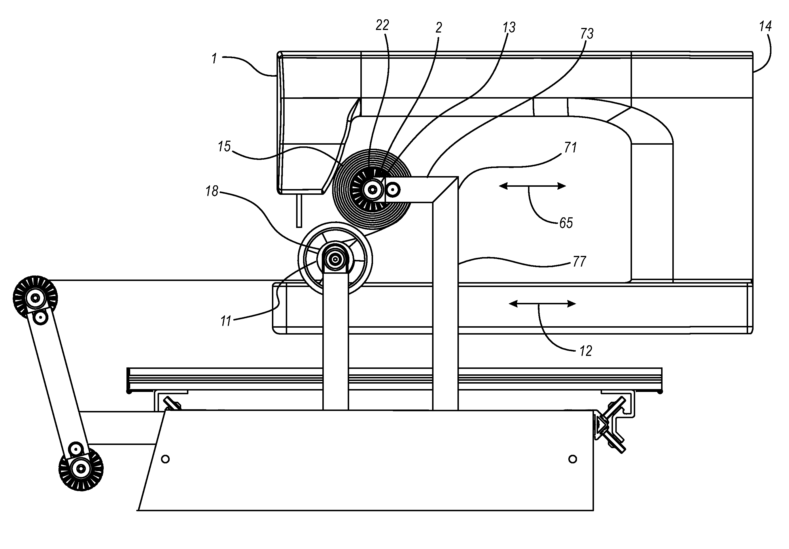
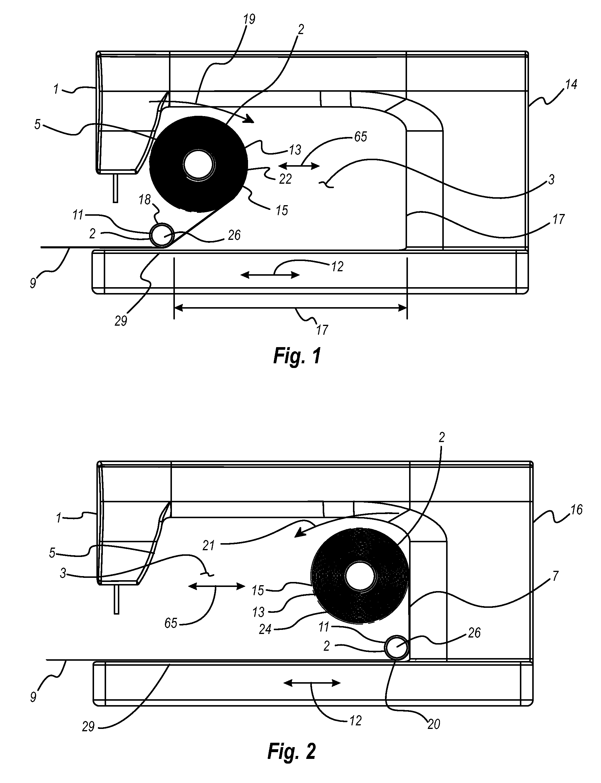
[0037]Referring first to FIG. 1, a side view cross section of a preferred embodiment of a take-up rail assembly 2 of the present invention deployed with a typical sewing machine 1 is shown. The sewing machine 1 illustrated is a typical quilting machine which may be mounted on a quilting frame 34, an embodiment of which is shown in FIG. 9, which provides for back and forth longitudinal movement 12 as well as lateral movement of the sewing machine, as the sewing operation is under way, thereby providing for the sewing machine to sew a pattern in the fabric or layers of fabric 9 being sewn.

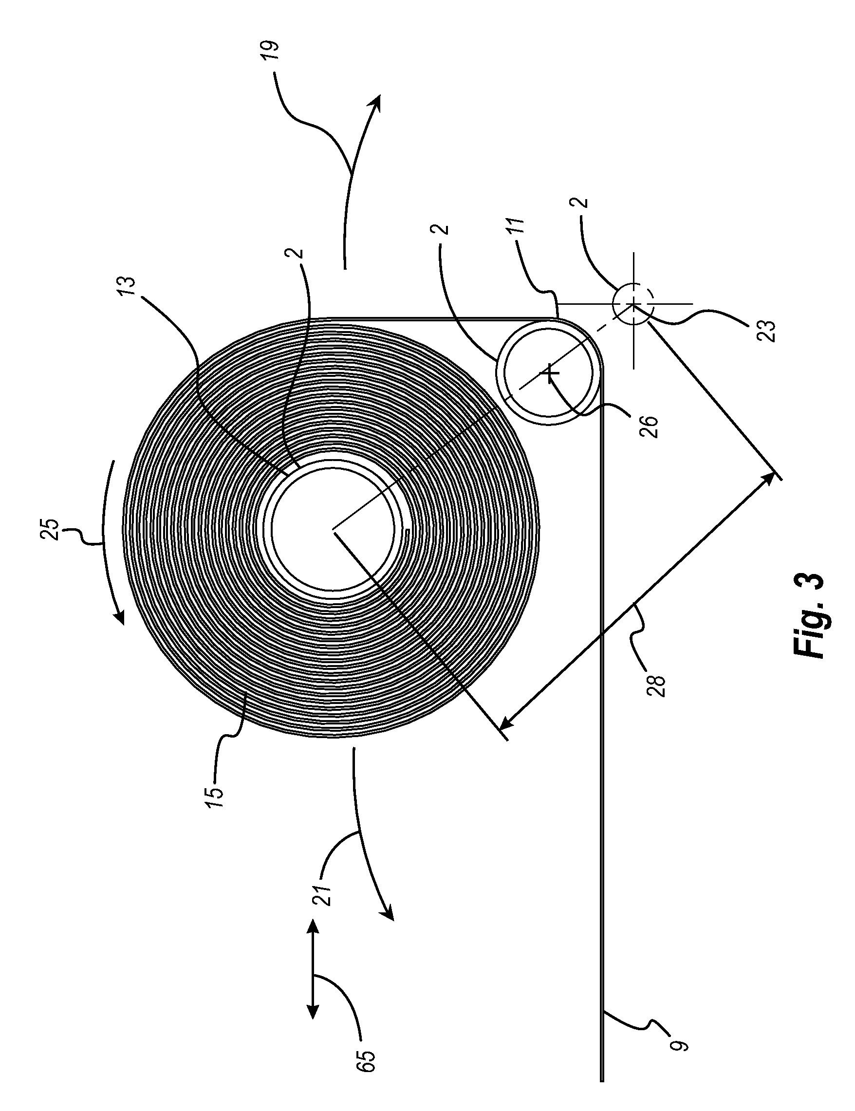
[0038]In the case of a typical quilting sewing operation, the fabric layers 9 consist of a quilt front, a quilt back, and backing material. The take-up rail assembly 2 illustrated in FIG. 1 includes a fixed idler rail 11 and a longitudinally movable take-up rail 13. For the preferred embodiment shown in FIG. 1, take-up rail longitudinal movement 65 is provided by pivoting of the take-up rail 19,21 as...


PUM


Abstract

A take-up rail assembly including a fixed idler rail and a longitudinally movable take-up rail. The fixed idler rail is attached to a quilting frame or other sewing frame and the position of the fixed idler rail may be longitudinally and vertically adjustable with respect to the sewing frame. The take-up rail is movably attached to the sewing frame and a take-up rail control mechanism moves the take up rail longitudinally forward and rearward with respect to the fixed idler rail as the sewing machine moves with respect to the sewing frame, thus providing full utilization of the throat length of the sewing machine.

Description

FIELD OF THE INVENTION[0001]This invention is in the field of sewing machine accessories and in particular in the field of take-up rail assemblies for quilting frames.BACKGROUND OF THE INVENTION[0002]A quilt is usually sewn from three layers, a pre-sewn and pieced top fabric, a fabric backing bottom layer, and batting in the middle of the two fabric layers. Machine quilting is traditionally accomplished using one of two methods. For the first method, a user uses a sewing machine on a table and pushes the entire quilt around to quilt the three layers, which is cumbersome and difficult to manipulate.[0003]For the second method, a user uses a quilting frame with a sewing or quilting machine mounted on it. For this method, the quilting frame typically consists of a system of four or five separate rails to manage the three layers of fabric. At the front of the frame there are three rails. Each rail has one of the three quilt layers of fabric rolled onto it. The three rails feed the three...

Claims


Application Information

Patent Timeline
Patent Type & Authority Patents(United States)
IPC IPC(8): D05B35/00D05B11/00D05B21/00D05B35/04
CPCD05B11/00D05B35/04D05B21/00
Inventor BAGLEY, JIM MATTHEWS
Owner GRACEWOOD MANAGEMENT
Why Eureka
Try Eureka