Electromagnetic actuator

a technology of electromagnetic actuator and actuator body, which is applied in the direction of valve details, valve arrangement, machines/engines, etc., can solve the problems of affecting the movement of the movable core by oil and/or extraneous materials, and affecting the stability so as to increase the sliding resistance between the movable core and the fixed core, the effect of high response of the movable core and the higher viscosity of oil

Active Publication Date: 2017-05-16
DENSO CORP
View PDF20 Cites 3 Cited by
  • Summary
  • Abstract
  • Description
  • Claims
  • Application Information

AI Technical Summary

Benefits of technology

[0010]The present disclosure is made in view of the above problems. It is an object of the present disclosure to provide an electromagnetic actuator for driving a hydraulic control valve, wherein reliability of the actuator is increased.
[0012]According to the above feature, it is possible to prevent the oil of high pressure injected from the oil-discharge port from rushing into the movable-core chamber through the air breathing passage. It is, therefore, possible that a rod fixed to a movable core maintains its force for pushing the hydraulic control valve.
[0013]It is also possible to prevent the oil of a grease-like condition from flowing into the movable-core chamber through the air breathing passage, even when viscosity of the oil is increased at a low surrounding temperature. Accordingly, it is possible to avoid a situation that sliding resistance between the movable core and a fixed core is increased due to higher viscosity of the oil. It is, therefore, possible to keep a high response of the movable core with respect to electric power supply to an electromagnetic coil.
[0014]In addition, since an increase of amount of the oil flowing into the movable-core chamber is prevented, it is possible to suppress an increase of amount of the extraneous material contained in the oil and flowing into the movable-core chamber. As a result, the sliding resistance between the movable core and the fixed core is decreased to thereby increase reliability of the electromagnetic actuator for driving the hydraulic control valve.

Problems solved by technology

Since air passes through the air breathing passage, the air in the movable-core chamber does not prevent a smooth movement of the movable core.
Therefore, it may become a problem that the oil from the oil-discharge port and / or extraneous material contained in the oil directly flows into the movable-core chamber through the air breathing passage.
As a result, it may become difficult for a rod fixed to the movable core to keep its force for pushing the hydraulic control valve.
Furthermore, when an amount of the oil flowing into the movable-core chamber is increased, and when an amount of the extraneous material contained in the oil and flowing into the movable-core chamber is correspondingly increased, it may become a problem that a sliding movement of the movable core is adversely affected by such oil and / or the extraneous material.

Method used


Image

  • Electromagnetic actuator
  • Electromagnetic actuator
  • Electromagnetic actuator

Examples


first embodiment

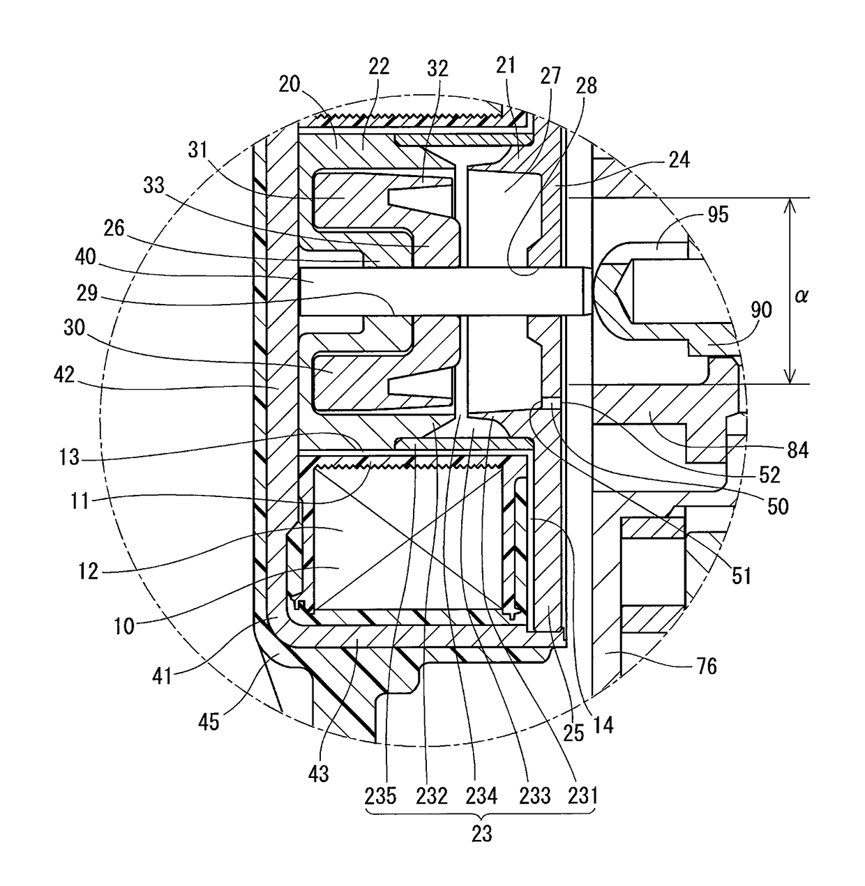
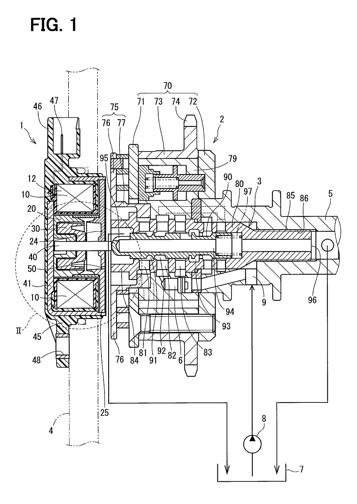
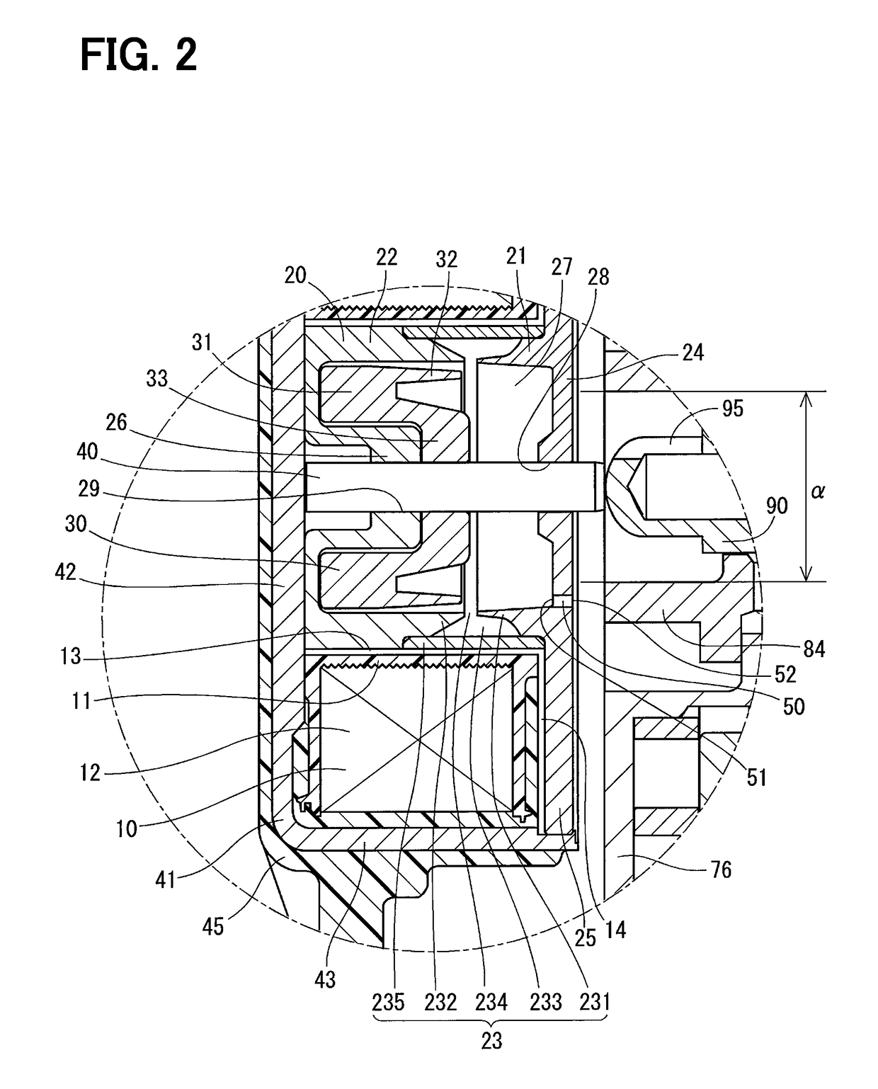
[0028]An electromagnetic actuator 1 according to a first embodiment of the present disclosure is shown in FIGS. 1 to 3. The electromagnetic actuator 1 (hereinafter, the actuator 1) is provided at a position opposing to a hydraulic control valve 3, which is fixed to a rotational center of a valve timing control device 2, in order to drive the hydraulic control valve 3.

[0029]The valve timing control device 2 is rotated in synchronism with a crank shaft of an internal combustion engine and rotated together with a cam shaft 5. Working fluid is supplied to the valve timing control device 2 via the hydraulic control valve 3, so that the valve timing control device 2 controls a relative rotational phase between the crank shaft and the cam shaft 5.

[0030]A structure of the actuator 1 will be explained at first. The actuator 1 is composed of an electromagnetic coil 10 (hereinafter, the coil 10), a fixed core 20, a movable core 30, a rod 40, a yoke 41, a molded body 45, an air breathing passag...

second embodiment

[0077]An electromagnetic actuator according to a second embodiment will be explained with reference to FIG. 4.

[0078]In the actuator of the second embodiment, an air breathing passage 53 is declined to the lower side in the direction of gravitational force, when the air breathing passage 53 extends from the inner wall of the movable-core chamber 27 toward the outside of the actuator (that is, from the inside opening 51 to the outside opening 52). Therefore, the outside opening 52 is located at a position lower than that of the inside opening 51 in the direction of gravitational force.

[0079]The outside opening 52 of the air breathing passage 53 is located at such a position, which is further away from the circular area “α” (the oil splashing area), to which the oil discharged from the oil-discharge port 95 of the hydraulic control valve 3 is directly splashed, than the outside opening 52 of the first embodiment.

[0080]The oil discharged from the oil discharge-port 95 becomes closer to ...

third embodiment

[0083]An electromagnetic actuator according to a third embodiment will be explained with reference to FIG. 5.

[0084]In the third embodiment, an air breathing passage is composed of the gap 234 between the first and second cylindrical members 21 and 22, the space 233 between the first and second thin-walled portions 231 and 232, and a through-hole 54 penetrating through the first cylindrical member 21 in the axial direction.

[0085]In the present disclosure, the gap 234 between the first and second cylindrical members 21 and 22 is also referred to as a first passage portion, the space 233 between the first and second thin-walled portions 231 and 232 is also referred to as a communicating passage portion, and the through-hole 54 penetrating through the first cylindrical member 21 in the axial direction is also referred to as a second passage portion.

[0086]In addition, an opening end of the gap 234 on a side to the movable-core chamber 27 is also referred to as an inside opening portion. ...


PUM


Abstract

An electromagnetic actuator, which is arranged at a position opposing to a hydraulic control valve, has a movable-core chamber for movably accommodating a movable core and an air breathing passage for communicating the movable-core chamber to the atmosphere. An inside opening of the air breathing passage is formed in an inner wall of the movable-core chamber, while an outside opening of the air breathing passage is formed in an outer wall of the actuator, which is in contact with the atmosphere. The outside opening is formed at such a position out of an oil-splashing area, to which oil discharged from an oil-discharge port of the hydraulic control valve is directly splashed. According to the above structure, it is possible to prevent the oil discharged from the oil-discharge port from rushing into the movable-core chamber through the air breathing passage.

Description

CROSS REFERENCE TO RELATED APPLICATION[0001]This application is based on Japanese Patent Application No. 2013-080442 filed on Apr. 8, 2013, the disclosure of which is incorporated herein by reference.FIELD OF TECHNOLOGY[0002]The present disclosure relates to an electromagnetic actuator, which is used for a valve timing control device of an internal combustion engine.BACKGROUND[0003]An electromagnetic actuator for driving a hydraulic control valve, which is provided in a rotational center of a valve timing control device for an internal combustion engine, is known in the art.[0004]In a prior art, for example, disclosed in German Patent Publication DE 10 2010 060 180 A1, an electromagnetic actuator is provided at a position opposing to a hydraulic control valve and a rod connected to a movable core pushes a spool of the hydraulic control valve when electric power is supplied to an electromagnetic coil. On the other hand, when the electric power supply to the electromagnetic coil is cu...

Claims


Application Information

Patent Timeline
Patent Type & Authority Patents(United States)
IPC IPC(8): F16K31/02F01L1/344F02D13/02F16K31/06
CPCF16K31/0675F01L1/3442F02D13/02F01L2001/3443F01L2001/34433F01L2001/34469F01L2101/00F01L2810/02F01L2301/00
Inventor ARAO, MASASHI
Owner DENSO CORP
Why Eureka
Try Eureka