Winding mechanism, top rail assembly and window blind

a top rail assembly and window blind technology, applied in the field of window blinds, can solve the problems of generating problems, unable to achieve the balance of the spring driver, and a potential strangulation hazard for children, and achieve the effects of reducing cost, simple assembly, and easy operation

Active Publication Date: 2018-11-13
ZHANG HUICAI
View PDF13 Cites 3 Cited by
  • Summary
  • Abstract
  • Description
  • Claims
  • Application Information

AI Technical Summary

Benefits of technology

[0007]One objective of the present invention is to provide a winding mechanism with a simple structure, which changes force moments of a pull rope on the winding mechanism thus to maintain a substantially equal and balanced force of a hand during operations to the window blind, accordingly to bring an effortless and quick operations of retracting and extending, furthermore, the window blind may not rebound or fall once the hand is loosed.
[0008]Another objective of the present invention is to provide a top rail assembly fir a window blind having a winding mechanism, which changes force moments of a pull rope on the winding mechanism thus to maintain a substantially equal and balanced farce of a hand during operations to the window blind, accordingly to bring an effortless and quick operations of retracting and extending, furthermore, the window blind may not rebound or fall once the hand is loosed.
[0009]One more objective of the present invention is to provide a window blind having a winding mechanism, which changes force moments of a pull rope on the winding mechanism thus to maintain a substantially equal and balanced force of a hand during operations to the window blind, accordingly to bring an effortless and quick operations of retracting and extending, furthermore, the window blind may not rebound or fall once the hand is loosed.
[0023]In comparison with the prior art, the window blind of the present invention supplies a roller with a tapered diameter to change the force moment of the pull rope on the roller, so as to make a pulling three and a lifting force of a hand applying to the window blind substantially constant and balanced, therefore an effortless and quick operation to pull or lift the window blind is obtained, and no rebound or no falling problem happens. In comparison of the conventional ones, the present invention has reduced cost and simple assembly to save time and manpower, the using life is extended, and the manufacturing method is easy, which is desired by the manufacturers.

Problems solved by technology

Due to restrictions of the blinds system and driving manner, the pull rope is longer than the total length of the window blinds after the window blinds are retracted, which brings potential strangulation hazard to children.
However, such a balance is difficult to achieve by the spring driver.
Thus some problems will be generated if the lift force provided by the spring driver is constant.
Under this situation, the window blind may not be maintained at the top position, but fall down slowly.
However, the above structures are complicated and the cost is increased.
In the mass production, the frictions become indefinite due to assembling process and different using ways, thus the rebound force, the frictions and the gravity may still mismatch to bring the unbalanced force.

Method used


Image

  • Winding mechanism, top rail assembly and window blind
  • Winding mechanism, top rail assembly and window blind
  • Winding mechanism, top rail assembly and window blind

Examples


Embodiment Construction

[0031]Various preferred embodiments of the invention will now be described with reference to the figures, wherein like reference numerals designate similar parts throughout the various views.

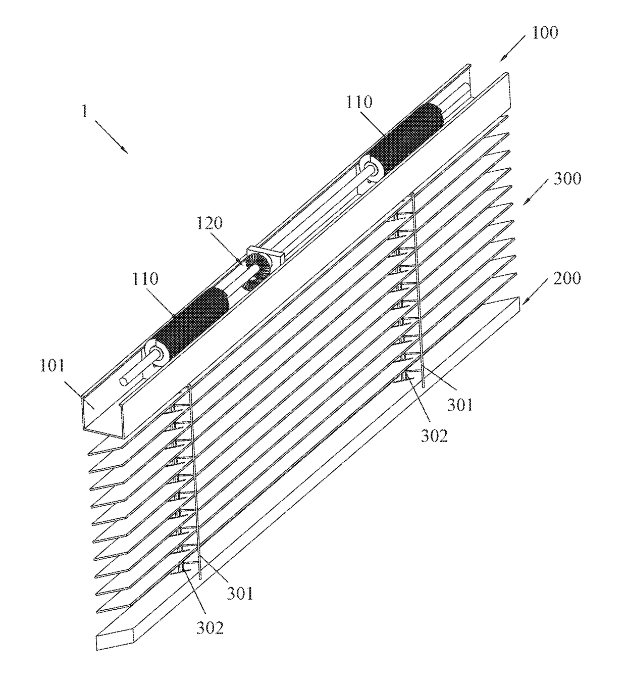
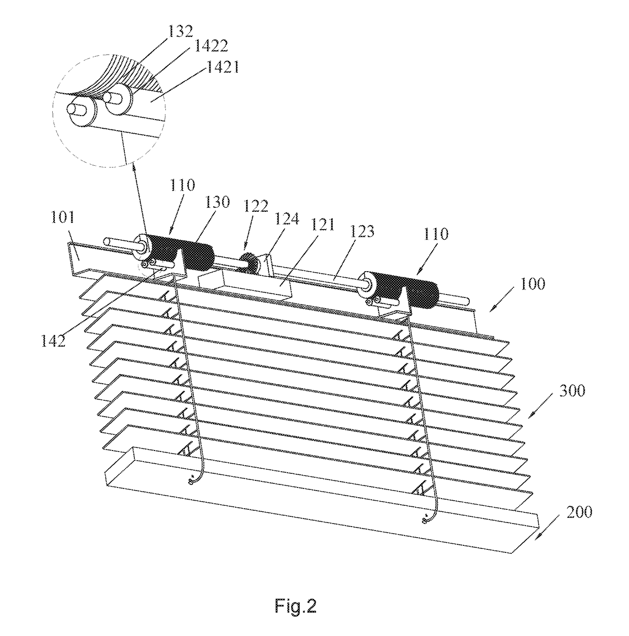
[0032]Referring to FIGS. 1 and 2, a window blind 1 includes a top rail assembly 100, a bottom rail 200 and multiple slats 300 connected between the top rail assembly 100 and the bottom rail 200. The slats 300 will be extended if the bottom rail 200 is pulled down by a hand and will be extended if the bottom rail 200 is lifted up by a hand.

[0033]The slats 300 are connected and supported by a trapezoidal rope 301 extended between the top rail assembly 100 and the bottom rail 200, and a pull rope 302 is extended from the bottom rail 200 to the top rail assembly 100, runs through the slats 300 and winds around the top rail assembly 100.

[0034]Specifically, the top rail assembly 110 includes at least one winding mechanism 110 and a driving unit 120, which are installed in a U-shape rail 101 of the top...


PUM


Abstract

A winding mechanism adapted for window blinds includes a shaft and at least one spiral groove configured on the shaft. The shaft has a wider first end and a narrower second end, and a diameter of the shaft is gradually reduced from the wider first end to the narrower second end, one end of a pull rope is connected with the shaft, and the other end of the pull rope is connected with slats, the pull rope in turn winds around the spiral groove from the wider first end to the narrower second end, or in turn disengages from the spiral groove from the narrower second end to the wider first end. The force moment of the pull rope is varied with the diameter of the shaft, thereby an effortless and quick operation to pull or lift the window blind is obtained, and no rebound or no falling problem happens.

Description

RELATED APPLICATIONS[0001]This application claims the benefit of priority to Chinese Invention Application No. 201710146625.2, filed Mar. 13, 2017, which is hereby incorporated by reference in its entirety.FIELD OF THE INVENTION[0002]The present invention relates to window blinds, and more particularly to a winding mechanism, a top rail assembly and a window blind including the same.BACKGROUND OF THE INVENTION[0003]In conventional window blinds, multiple slats are connected trapezoidal ropes that are extended between a top rail and a bottom rail, one or more pull ropes run through the slats and extend from the bottom rail to the top rail. The bottom rail will be raised towards the top rail under an upward force applied to the pull rope, in such a way the slats will be retracted from bottom to top. Due to restrictions of the blinds system and driving manner, the pull rope is longer than the total length of the window blinds after the window blinds are retracted, which brings potentia...

Claims


Application Information

Patent Timeline
Patent Type & Authority Patents(United States)
IPC IPC(8): E06B9/322
CPCE06B9/322E06B2009/3227E06B2009/3222E06B9/326
Inventor ZHANG, HUICAI
Owner ZHANG HUICAI
Why Eureka
Try Eureka