Backplane optical connectors and optical connections incorporating the same

a backplane and optical connector technology, applied in the field of optical connectors, can solve the problems of unresolved need to provide server blades or cards, costly optical connections, and costly internal optical jumpers to facilitate board-side optical connections

Active Publication Date: 2019-07-16
CORNING OPTICAL COMM LLC
View PDF66 Cites 3 Cited by
  • Summary
  • Abstract
  • Description
  • Claims
  • Application Information

AI Technical Summary

Benefits of technology

[0009]In embodiments described herein, the circuit board optical connector is rigidly coupled to the edge of the circuit board, while one or more components of the backplane optical connector floats with respect to the backplane. This allows the backplane optical connector to be active, and to move to the circuit board optical connector of the incoming circuit board. Magnets are utilized to both provide the attractive force for initiating the float (i.e., movement) in the backplane optical connector as well as to maintain the mating force between the circuit board optical connector and the backplane optical connector.

Problems solved by technology

As bandwidth demands increase there is an unresolved need to provide server blades or cards that can transmit high-speed optical signals.
Such optical connections may be costly due to the precise alignment requirements needed between the mated optical connectors.
In some cases, costly internal optical jumpers are required to facilitate board-side optical connections.
These internal optical jumpers not only add cost, but also introduce optical loss.

Method used


Image

  • Backplane optical connectors and optical connections incorporating the same
  • Backplane optical connectors and optical connections incorporating the same
  • Backplane optical connectors and optical connections incorporating the same

Examples


Embodiment Construction

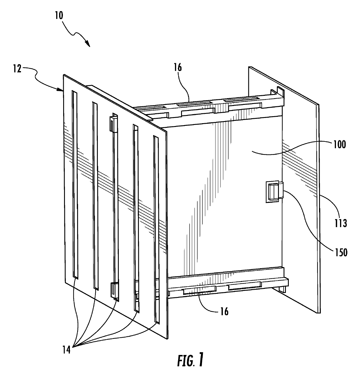
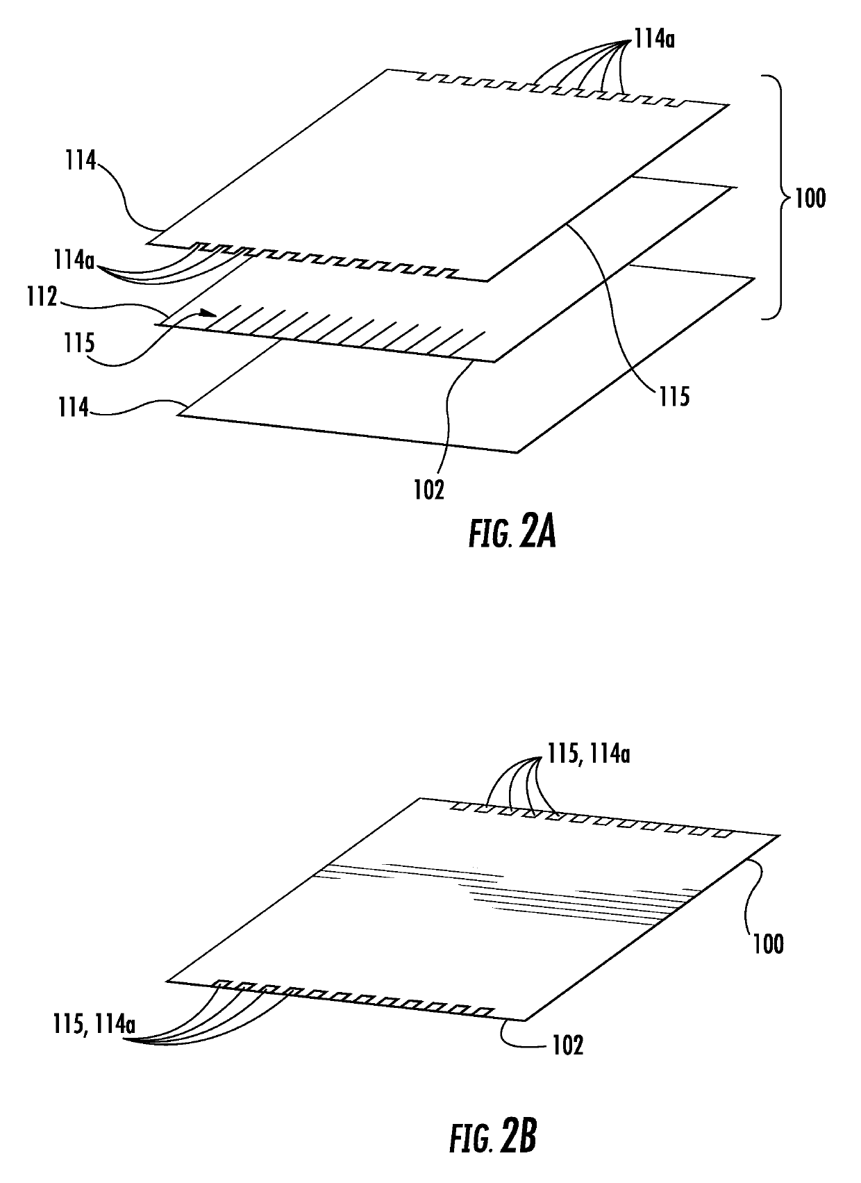
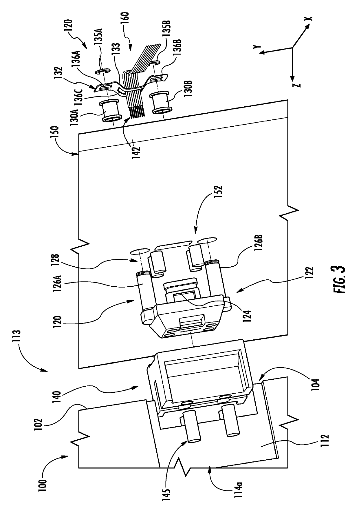
[0038]Embodiments are directed to optical connectors and, more particularly, to backplane optical connectors and optical connections for edge-wise optical coupling of circuit boards to backplane structures. As an example and not a limitation, the backplane optical connectors and optical connections described herein may be employed in rack-based equipment, such as racks employed in data distribution centers and telecommunications applications. A floatable optical connector is employed on the backplane side, while a rigid optical connector is provided on the edge of the circuit board. Magnets are utilized to both provide the attractive force for initiating the float (i.e., movement) in the backplane optical connector as well as to maintain the mating force between the circuit board optical connector and the backplane optical connector. When the edge of the circuit board is brought into close proximity with the backplane, the backplane optical connector advances toward the circuit boar...


PUM


Abstract

Backplane optical connectors and optical connections are disclosed herein. In one embodiment, a backplane optical connector includes a ferrule element that includes a body portion having optical interface, at least two bores positioned through the body portion, at least two posts extending from the body portion, and a fiber inlet portion extending from the body portion. The fiber inlet portion includes a fiber receiving opening. The backplane optical connector further includes a magnet disposed within each bore of the at least two bores, and a bias member coupled to the at least two posts.

Description

BACKGROUND[0001]Field[0002]The present disclosure generally relates to optical connectors and, more particularly, to optical connectors that optically couple components of a circuit board to a components of a backplane.[0003]Technical Background[0004]Benefits of devices having optical waveguides include extremely wide bandwidth and low noise operation. Because of these advantages, devices with optical waveguides are increasingly being used for a variety of applications, including but not limited to broadband voice, video, and data transmission. For example, fiber optic networks employing optical fiber are being developed and used to deliver voice, video, and data transmissions to subscribers over both private and public networks.[0005]For example, optical fiber may be employed in data distribution centers or central offices for telecommunications and storage systems applications. These applications include, but are not limited to, server farms, such as for web page accesses, and rem...

Claims


Application Information

Patent Timeline
Patent Type & Authority Patents(United States)
IPC IPC(8): G02B6/40G02B6/38G02B6/42G02B6/43G02B6/32
CPCG02B6/403G02B6/3882G02B6/3885G02B6/3886G02B6/3893G02B6/4206G02B6/4292G02B6/43G02B6/3897G02B6/3821G02B6/32
Inventor FORTUSINI, DAVIDE DOMENICOLUTHER, JAMES PHILLIPOVERCASH, JERALD LEE
Owner CORNING OPTICAL COMM LLC
Why Eureka
Try Eureka