Device for monitoring dimensional, shape, and positional tolerances of a mechanical workpiece

a technology of mechanical workpieces and devices, which is applied in the direction of measuring/indicating equipment, coils, electrical/magnetic means, etc., can solve the problem of not being able to obtain useful measuring results, and achieve the effect of high measuring precision and simple configuration

Inactive Publication Date: 2007-08-28
KNABEL HORST
View PDF8 Cites 2 Cited by
  • Summary
  • Abstract
  • Description
  • Claims
  • Application Information

AI Technical Summary

Benefits of technology

[0006]It is an object of the present invention to configure a device for monitoring the dimensional, shape, and positional tolerances of a mechanical workpiece in such a way that for a minimal height and a simple configuration a measuring travel as large as possible and a high measuring precision can be obtained.
[0008]With this configuration, a high measuring precision is provided with a simple configuration of the measuring probe and with a relatively large available measuring travel. A height of the inductive coils is only minimally greater than a measuring travel of the sensing stylus. In addition, the field of application is significantly broadened and the expenditure for assembly, maintenance and service is reduced.

Problems solved by technology

Even though the immersion depth of the deflector body correlated with the compensating measuring coil is manually adjustable, it remains unaffected by the measuring travel and thus the stroke of the sensing stylus.
As a result of the currents of different magnitude, the measuring probe is also differently loaded thermally so that with such a measuring probe, even at high electrical expenditure for linearization of the measuring values, no useful measuring results can be obtained.

Method used


Image

  • Device for monitoring dimensional, shape, and positional tolerances of a mechanical workpiece
  • Device for monitoring dimensional, shape, and positional tolerances of a mechanical workpiece
  • Device for monitoring dimensional, shape, and positional tolerances of a mechanical workpiece

Examples


Embodiment Construction

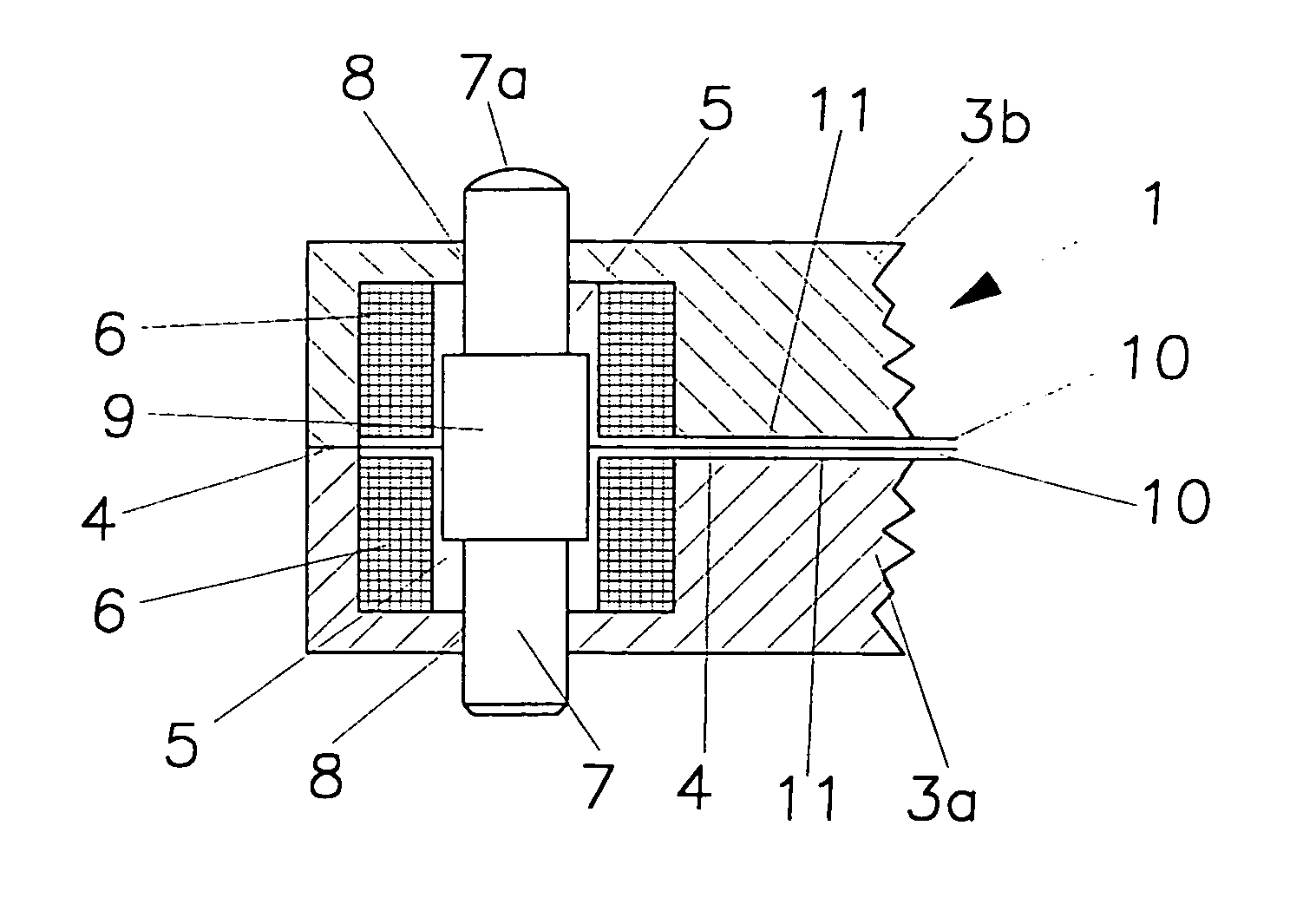
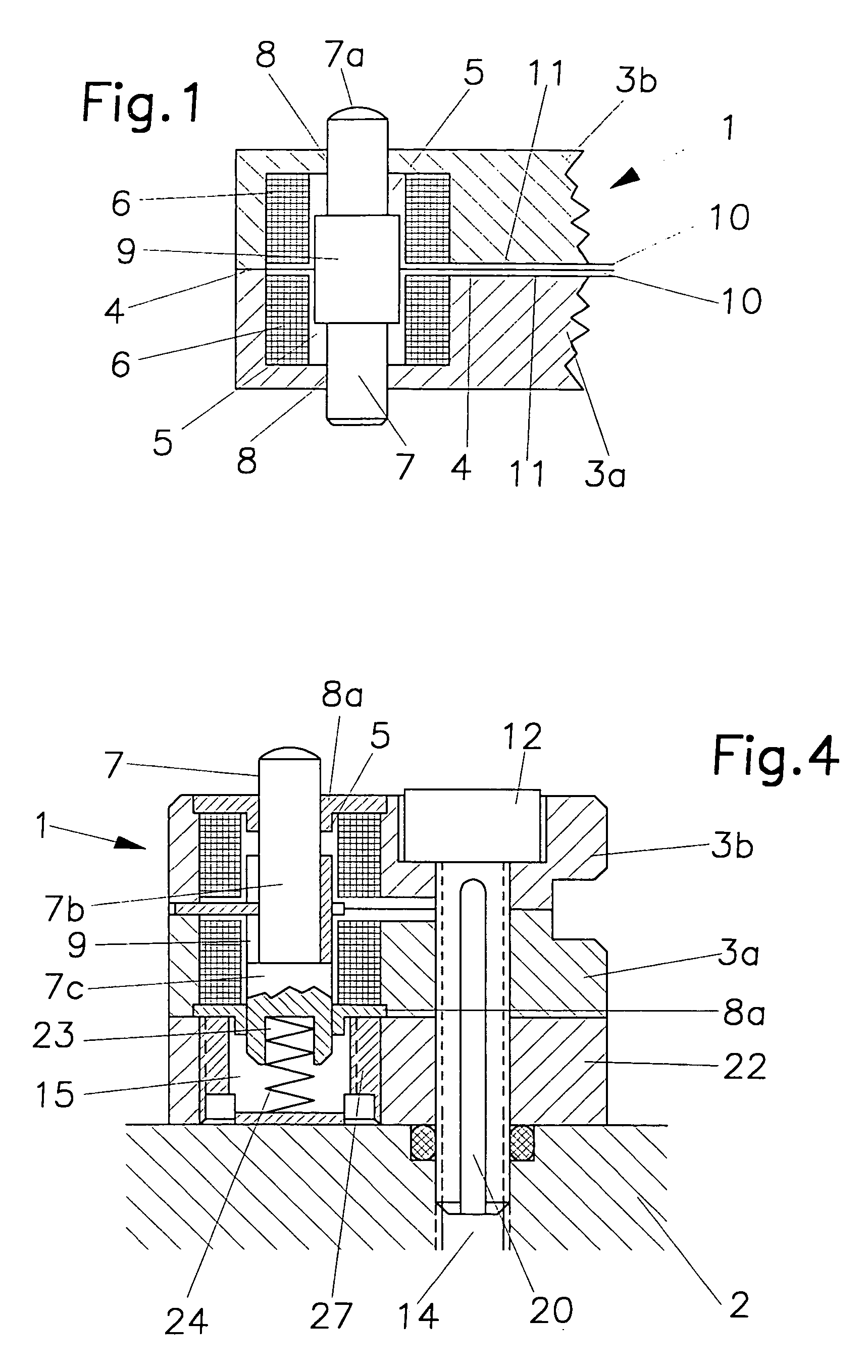
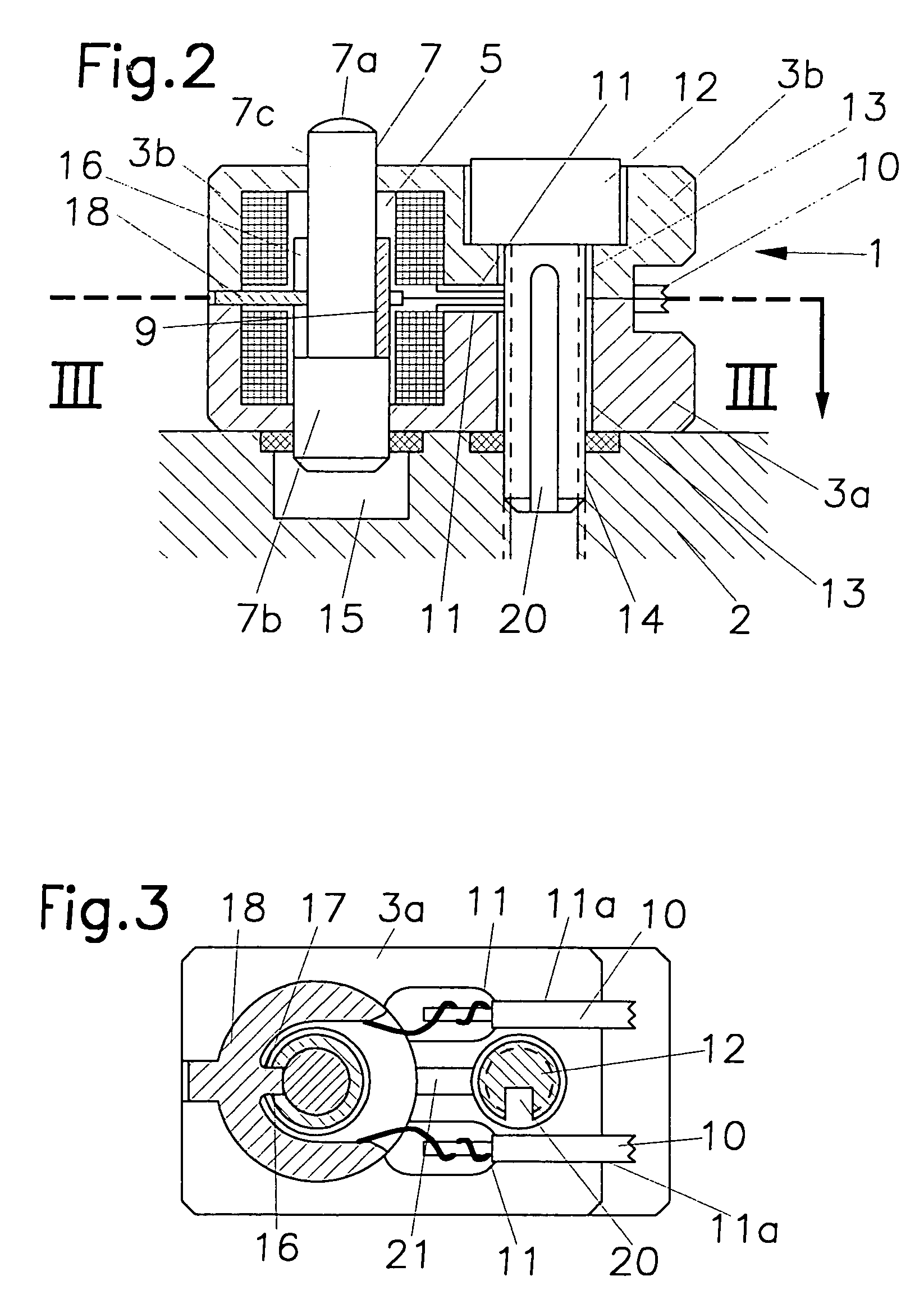
[0018]A measuring probe 1 is illustrated in FIGS. 1 to 4 and 5 of the drawing, respectively, and serves for monitoring the dimensions or dimensional deviations of a mechanical workpiece, not illustrated in the drawing. This measuring probe 1 is always comprised of a housing 3 that, according to the invention, is comprised of two shell-shaped housing parts 3a, 3b (FIG. 1). In this connection, the two housing parts 3a, 3b are advantageously fixedly connected to one another by gluing in the area of the plane surfaces 4 that are mirror-symmetrical to one another. For functional and manufacture-related reasons, it is expedient that both housing parts 3a, 3b are identical. Each of the two housing parts 3a, 3b has a cylindrical recess 5 that, toward the plane surfaces 4, is completely open; each recess receives an inductive coil 6. Both inductive coils 6 are aligned with one another and end advantageously at a minimal spacing relative to the plane surfaces 4.

[0019]In the interior of the tw...


PUM


Abstract

A device for monitoring the tolerances of a workpiece has a measuring probe with two separate inductive coils arranged in a housing. A non-magnetizable sensing stylus designed to rest on a workpiece surface to be measured is arranged in the coils and has a deflector body that is a sleeve. The stylus and the deflector body are loaded into a measuring position. The housing has two essentially identical housing halves each having a plane surface with which the housing halves are connected to one another. The housing halves each have a recess and one of the inductive coils is inserted into one of the recesses, respectively. The opposed ends of the housing halves are provided with aligned bores that open into the recesses, respectively. The stylus is arranged coaxially in the inductive coils and has opposed stylus ends projecting through the bores outwardly from the two housing halves.

Description

BACKGROUND OF THE INVENTION[0001]1. Field of the Invention[0002]The invention relates to a device for monitoring the dimensional, shape, and positional tolerances of a mechanical workpiece. The device comprises at least one measuring probe each having a housing, attached to a support, with two separate inductive coils and a sensing stylus resting on the surface to be measured of the workpiece and made of a non-magnetizable material. The stylus is embodied as a piston and supports a deflector body that is in the form of a sleeve, wherein the stylus together with the deflector body is movable by a force into its measuring position.[0003]2. Description of the Related Art[0004]Such a measuring probe is disclosed in German published patent application 195 12 836. In a housing of the measuring probe that is covered by a plate serving as a seal and a guide for the sleeve, a measuring inductive coil and a compensating inductive coil with outwardly extending connecting cables are positioned ...

Claims


Application Information

Patent Timeline
Patent Type & Authority Patents(United States)
IPC IPC(8): G01B7/02B23Q17/20G01D5/12G01B7/00G01D5/22
CPCG01B7/001G01D5/2225
Inventor KNABEL, HORST
Owner KNABEL HORST
Why Eureka
Try Eureka