Walker apparatus

a walker and seat technology, applied in the field of seatless glide type walkers, can solve the problems of no option for faster or easier movement, no walker providing safe, efficient propulsion of a user in an upright, standing position, and the use of such walker can become tedious, so as to achieve safe and efficient propulsion of the walker, stable operation of the walker, and the effect of efficient propulsion

Inactive Publication Date: 2010-06-10
MENEFEE ETHEL MAXINE
View PDF24 Cites 8 Cited by
  • Summary
  • Abstract
  • Description
  • Claims
  • Application Information

AI Technical Summary

Benefits of technology

[0009]The present invention overcomes the problems outlined above and provides a greatly improved walker which allows a recovering user to safely and efficiently propel the walker while standing. Generally speaking, the preferred walker of the invention includes a frame, with a plurality of wheels operably coupled with and supporting the frame, including a pair of laterally spaced apart wheels, so as to render the frame mobile. A foot plate is secured to the frame and oriented and operable for a user of the walker to stand with one of the user's feet on the foot plate in a substantially erect position and with the foot plate supporting substantially all of the user's weight. Propulsion of the walker is effected by the user's free foot periodically engaging the floor, allowing the user to “glide” between propulsion steps. In this way, the improved walker can far more efficiently be propelled than is the case with conventional designs.
[0010]In one aspect of the invention, the lower peripheries of the walker wheels lie in a common horizontal plane, and the foot plate is positioned in close proximity above this plane. This assures that the walker is stable during operation, as compared to a potentially unstable high placement of the foot plate. Normally, the foot plate is located at most only a few inches above the lower wheel periphery plane. In order to provide further safety, rearwardly extending outriggers are provided which prevent rear overturning of the walker.
[0011]In preferred forms, the foot plate is located in an offset relationship to the central fore and aft axis of the walker. This allows sufficient clearance within the confines of the walker for user propulsion as described.

Problems solved by technology

Use of such walkers can become tedious, particularly as a person becomes more mobile.
That is, each step forward requires a corresponding movement of the wheeled frame, with no option for faster or easier movement.
As can be appreciated from a study of these prior references, none provides a walker allowing safe, efficient propulsion thereof by a user in an upright, standing position.

Method used


Image

  • Walker apparatus
  • Walker apparatus
  • Walker apparatus

Examples


Embodiment Construction

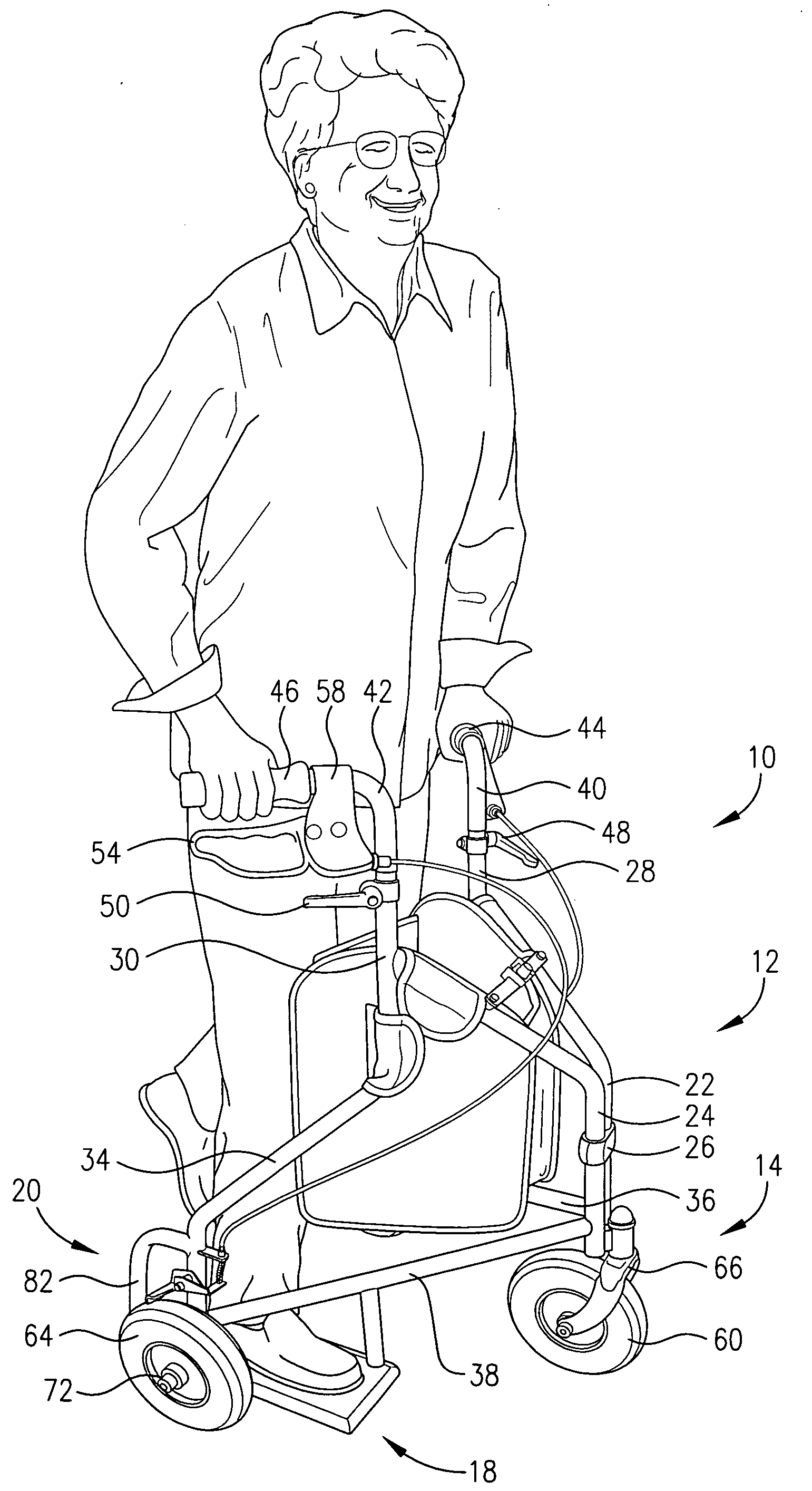
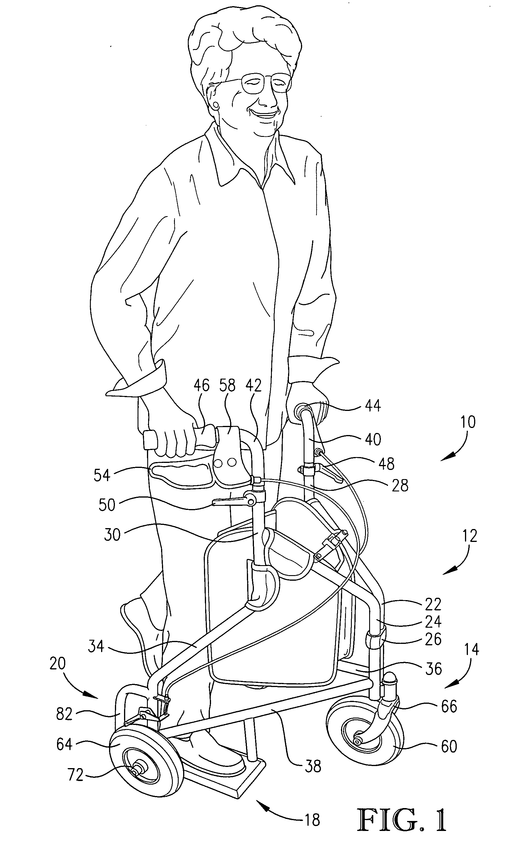
[0018]Turning now to the drawings, a walker 10 is illustrated which is designed for use by a person capable of standing in a substantially erect position during use of the walker.

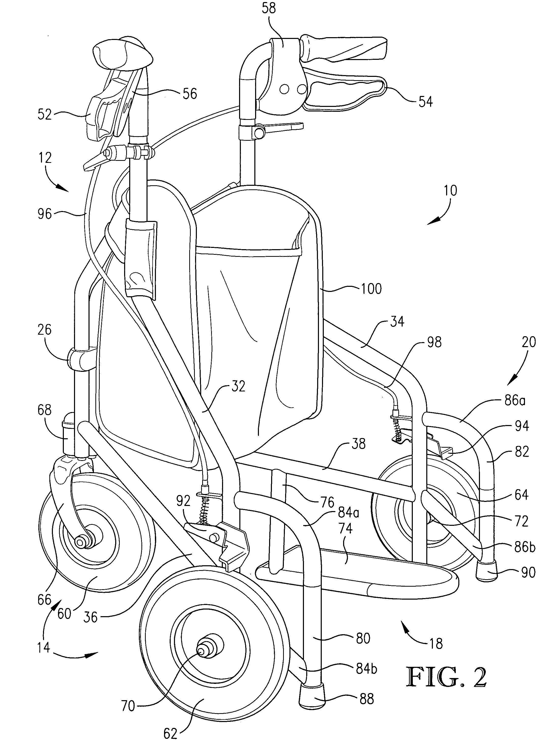
[0019]Broadly speaking, the walker 10 includes a rigid frame 12 supported by a plurality of wheels 14 allowing the walker to move across a support surface 16. The walker 10 further includes a rigid, offset foot plate 18 secured to frame 12, as well as a rearmost outrigger assembly 20.

[0020]In more detail, the frame 12 includes a pair of upright forward most members 22, 24 interconnected by means of band 26. The members 22, 24 diverge upwardly and outwardly above band 26 and have respective tubular uprights 28, 30 secured to the uppermost ends thereof. The uprights 28, 30 have individual downwardly extending segments 32, 34 forming the lower end of the frame 12. A pair of struts 36, 38 extend between each segment 32, 34 and the corresponding frame members 22, 24. A pair of generally L-shaped hand rails 40, 4...


PUM


Abstract

A seatless, multiple-wheel glide-type walker (10) is provided which has a frame (12) equipped with an offset foot plate (18) oriented for placement of a user's foot thereon in order to support substantially the entire weight of the user. The user's free foot can then be used to propel the walker (10) forwardly along a support surface (16). Rearmost outriggers (80, 82) secured to the frame (12) prevent inadvertent rear overturning of the walker (10). In practice, the user stands with one foot on the foot plate (18) and periodically pushes the walker (10) forwardly using the other foot, all while the user maintains a substantially erect position.

Description

BACKGROUND OF THE INVENTION[0001]1. Field of the Invention[0002]The present invention is concerned with improved, seatless glide-type walkers designed for use by recovering patients or other semi-invalids. More particularly, it is concerned with such walkers and associated methods wherein the walkers are equipped with a weight-supporting, offset foot plate allowing a user to stand upright with one foot on the foot plate and propel the walker forwardly using the free foot.[0003]2. Description of the Prior Art[0004]A wide variety of patient walkers have been provided in the past. Generally, these walkers include a lightweight, wheeled frame with upper hand grips allowing the user to grasp the frame and gain support while walking. Conventional walkers can be of a tricycle design with a forward swivel wheel and rear trailing wheels, or can be four-wheeled. Use of such walkers can become tedious, particularly as a person becomes more mobile. That is, each step forward requires a correspo...

Claims


Application Information

Patent Timeline
Patent Type & Authority Applications(United States)
IPC IPC(8): A61H3/04B62M1/00
CPCA61H3/04A61H2003/046A61H2003/005A61H2003/002
Inventor MENEFEE, ETHEL MAXINE
Owner MENEFEE ETHEL MAXINE
Why Eureka
Try Eureka