Enhanced efficiency pyrotechnic shell

Active Publication Date: 2005-05-26
AMERICAN PROMOTIONAL EVENTS
View PDF5 Cites 3 Cited by
  • Summary
  • Abstract
  • Description
  • Claims
  • Application Information

AI Technical Summary

Benefits of technology

[0009] In the preferred embodiment, the interior surface of the tube is cylindrical and the shape of the break at the bottom of the tube is likewise cylindrical, but of a slightly smaller diameter, such that upon ign

Problems solved by technology

Unfortunately, the spherical shape of the breaks in a conventional multiple stage pyrotechnic shell allows the expanding gases from the launch charge to escape between the breaks and the inner surface of the launch tube, resulting in substantial loss of pressure during launch.
This limits the launch height of a conventional multiple stage pyrotechnic shell.
The limited launch height of a conventional

Method used


Image

  • Enhanced efficiency pyrotechnic shell
  • Enhanced efficiency pyrotechnic shell
  • Enhanced efficiency pyrotechnic shell

Examples


Embodiment Construction

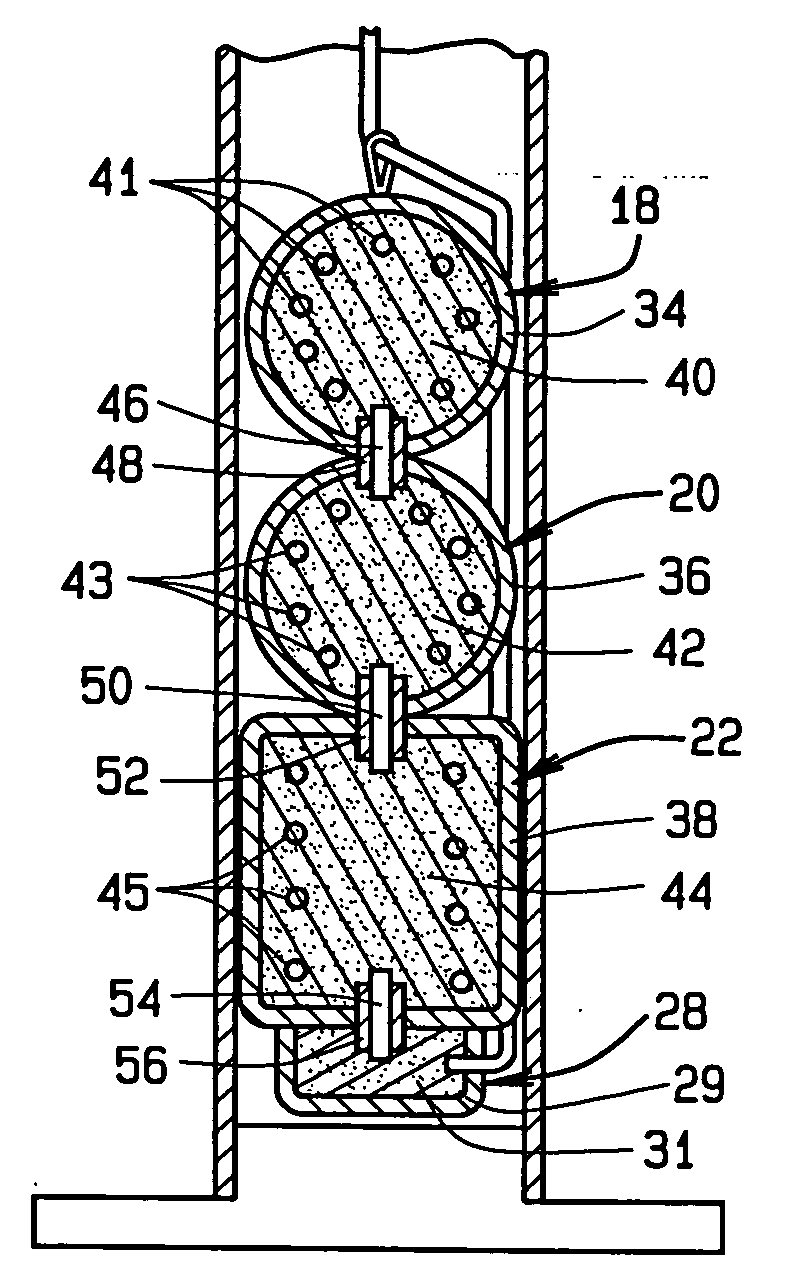
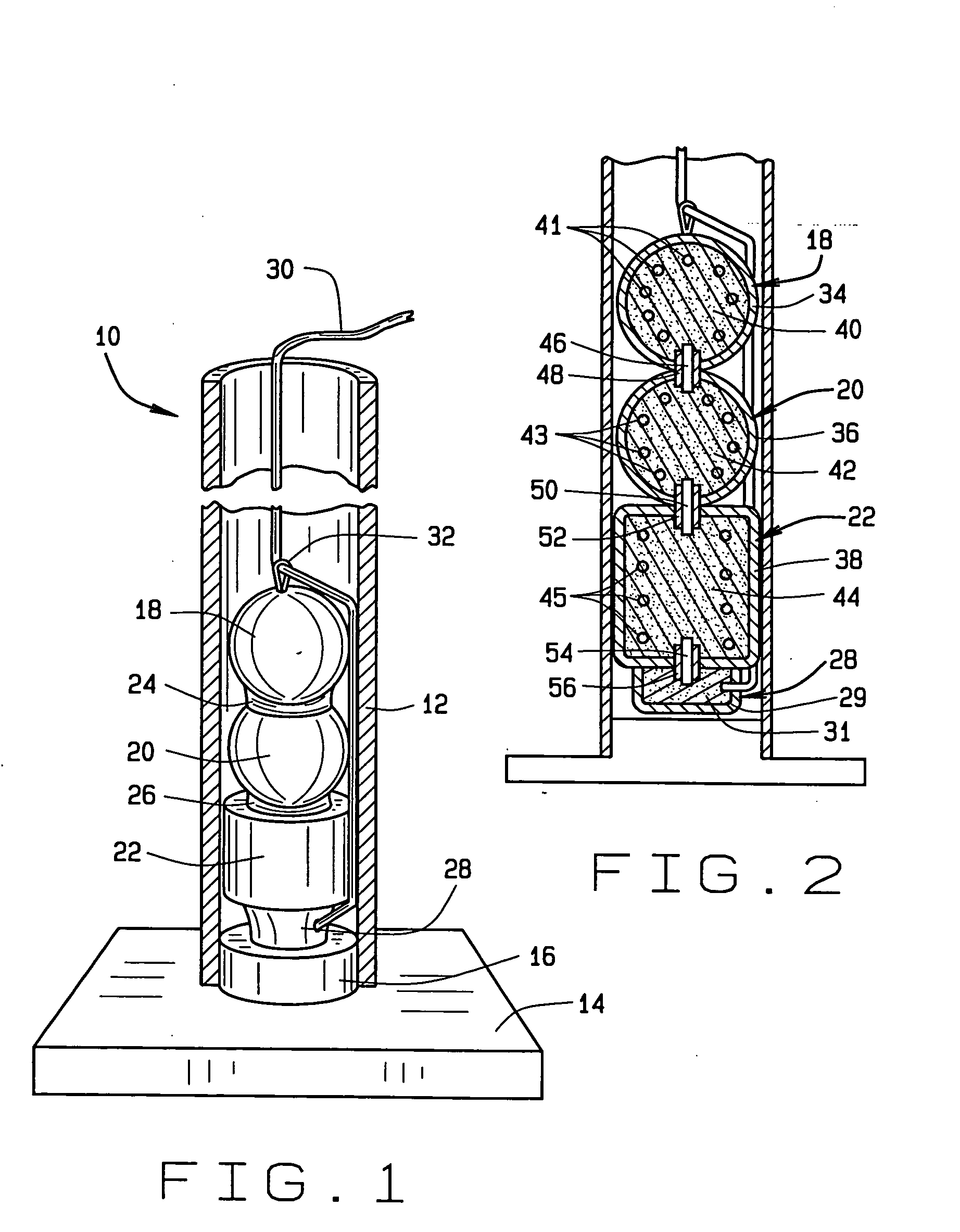
[0017] The multiple stage pyrotechnic shell apparatus of the preferred embodiment is indicated generally at 10 (FIG. 1). The shell 10 includes a tube 12, a generally flat base 14 positioned below the tube 12 and joined with the bottom of the tube 12, and a base plug 16 that is integral with and extending from the base 14, the plug 16 configured to fit snugly within and being secured to the inner surface of the bottom of the tube 12.

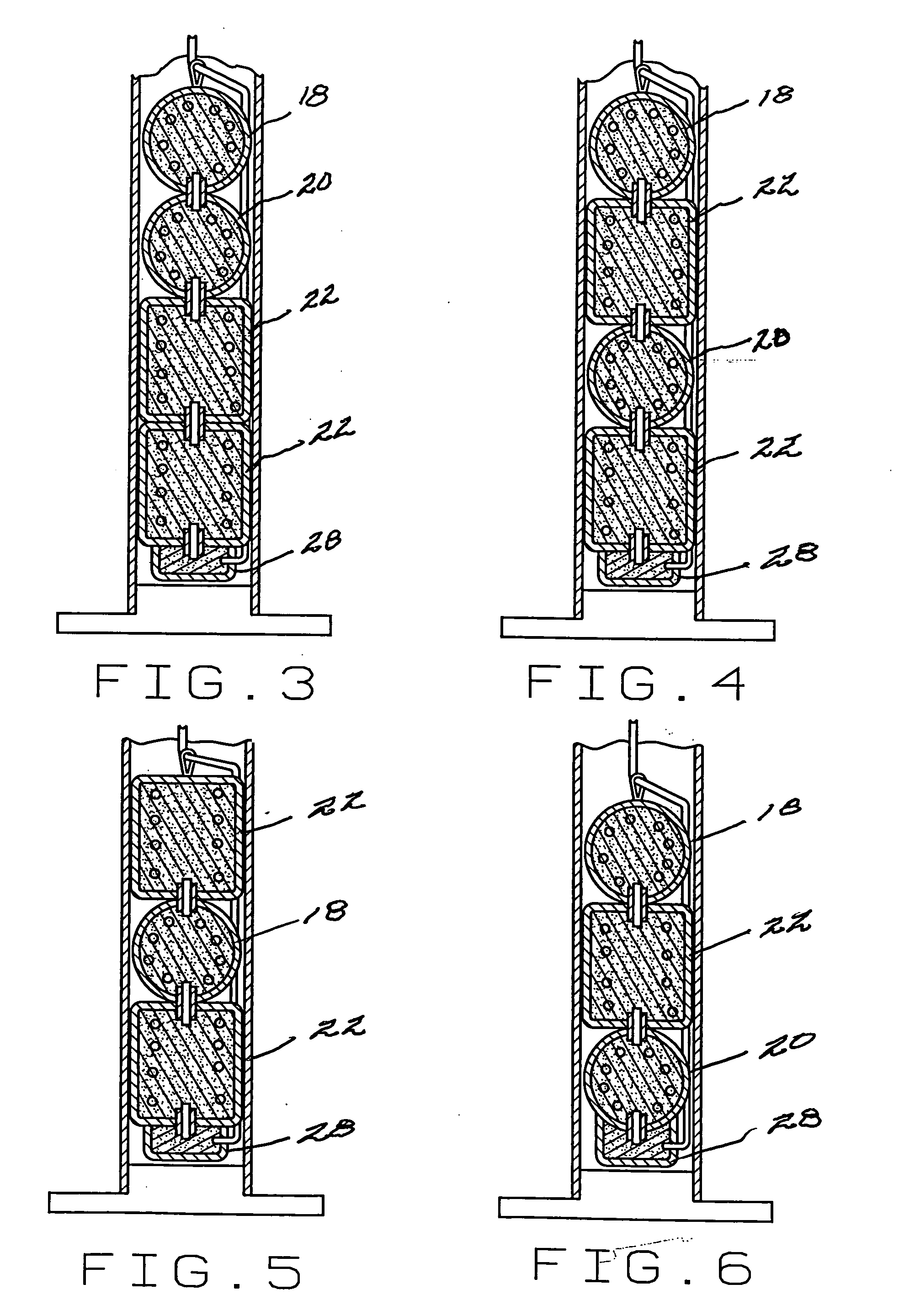
[0018] Three pyrotechnic breaks 18, 20, 22 are positioned sequentially within the tube 12, the cylindrical break 22 being positioned at the bottom of the tube 12 and the round breaks 18, 20 positioned above the break 22. The breaks 18, 20 are joined together with a paper connect 24 and the breaks 20, 22 are joined together with a paper connect 26. A lift charge compartment 28 is attached to the bottom of the cylindrical break 22 and rests against the top of the plug 16 within the tube 12.

[0019] A fuse 30 extends from the interior of the lift charge 28, ...


PUM


Abstract

A multiple stage pyrotechnic shell apparatus is disclosed. The invention has enhanced efficiency to increase lift and reduce the risk of one or more of the charges from exploding near the ground. The enhanced efficiency is obtained through the novel use of shaped breaks that conform to the shape of the inner surface of the shell's launch tube, and in particular through the use of cylindrically shaped breaks in round launch tubes. In addition, the present invention further enhances efficiency by configuring the breaks such that all the breaks weigh the same or the upper breaks weigh more than the lower breaks in the launch tube.

Description

CROSS REFERENCE TO RELATED APPLICATIONS [0001] This nonprovisional patent application claims priority to the provisional patent application having Ser. No. 60 / 485,914, which was filed on Jul. 10, 2003.BACKGROUND OF THE INVENTION [0002] The invention relates to a new pyrotechnic shell apparatus, and more particularly to a multiple stage pyrotechnic shell apparatus having enhanced efficiency to increase lift and reduce the risk of one or more of the charges from exploding near the ground. [0003] Multiple stage pyrotechnic shells typically comprise two or more pyrotechnic modules, known as “breaks” that are housed within a single launch tube. A launch charge is located in the tube below the breaks. The breaks are linked to one another and intended to sequentially discharge and produce a pyrotechnic effect once the breaks are launched a safe distance into the sky by the launch charge. Typically each of the breaks is configured in a spherical shape. [0004] Unfortunately, the spherical sh...

Claims


Application Information

Patent Timeline
IPC IPC(8): F42B4/02
CPCF42B4/02
Inventor YU, PETER
Owner AMERICAN PROMOTIONAL EVENTS
Why Eureka
Try Eureka