
Inertial propulsion device

Inactive Publication Date: 2008-10-23
LINEVICH EDVID IVANOVICH
View PDF0 Cites 2 Cited by
  • Summary
  • Abstract
  • Description
  • Claims
  • Application Information

AI Technical Summary

Benefits of technology

[0006]It is a primary object of the present invention to create an effective propulsion device having a reliable control system.
[0009]The unbalanced weight can be carried out as a cylindrical body set on the rotor axially to the rotor with the possibility to rotate freely in relation to the rotor.

Problems solved by technology

Thus the rotor is unbalanced concerning an axis of its rotation and is used as the unbalanced weight, and the stator is fixed rigidly on an axis installed on bearings coaxially to the rotor within the housing.

Method used


Image

  • Inertial propulsion device
  • Inertial propulsion device
  • Inertial propulsion device

Examples


Embodiment Construction

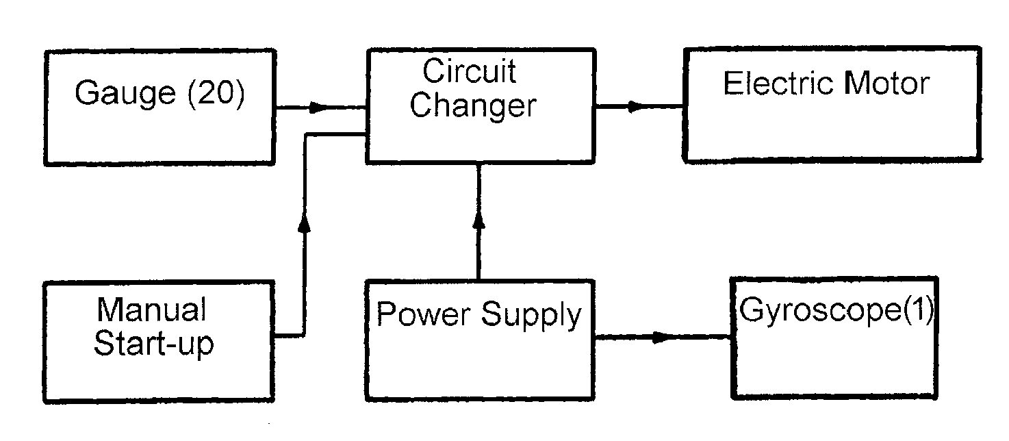
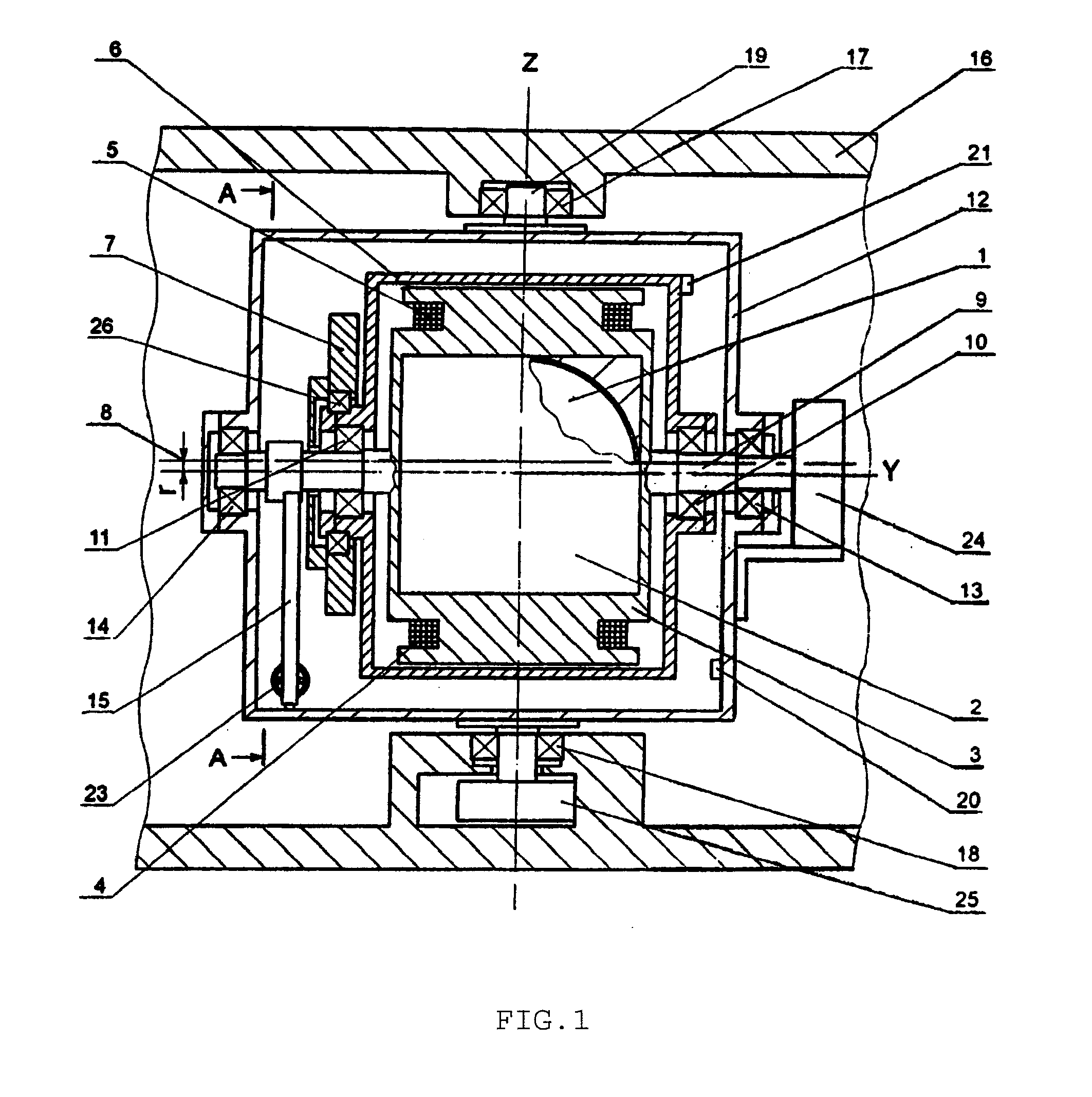
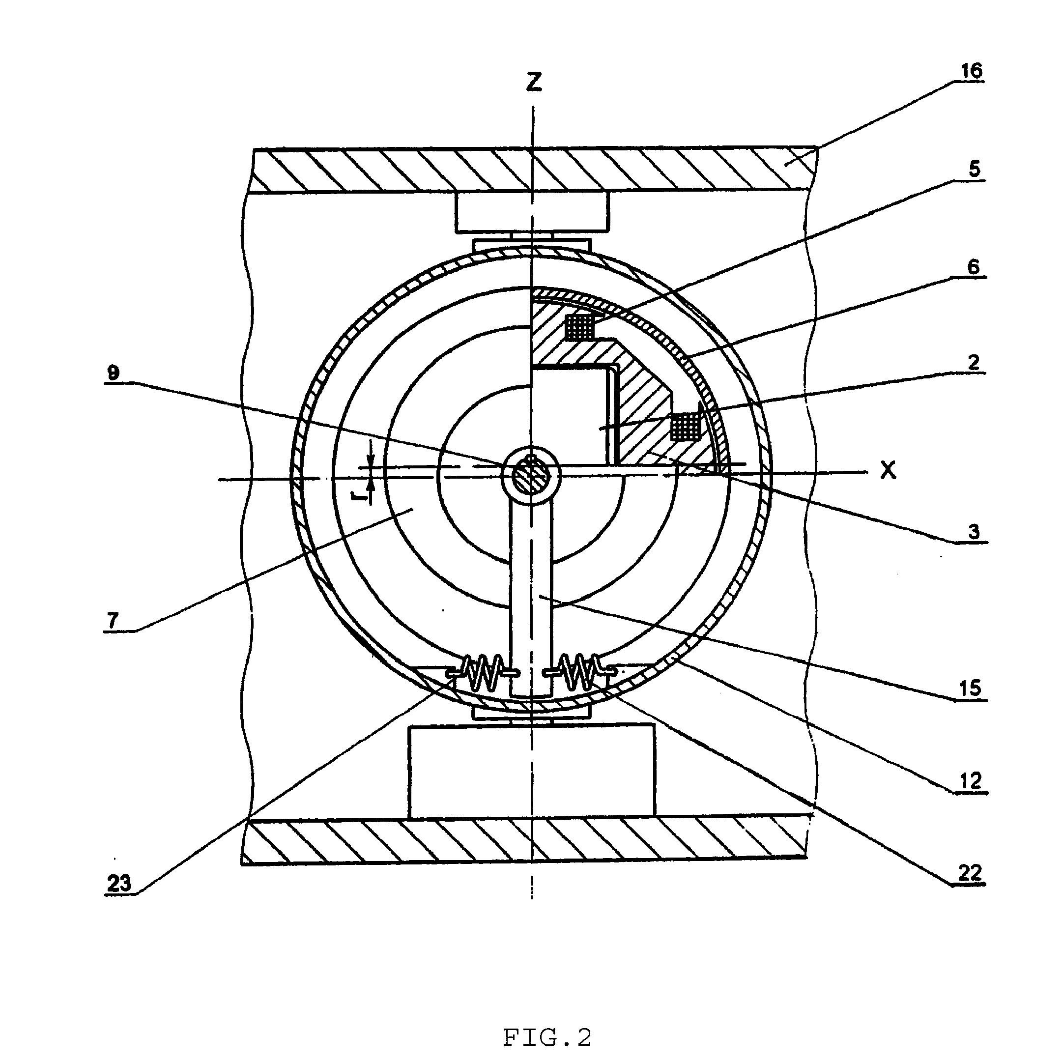
[0025]Following number references are used for drawings: 1—a gyroscope; 2—a case of the gyroscope; 3—a stator of an electric motor; 4 and 5—windings of the electric motor; 6—a rotor; 7—an unbalanced weight; 8—an axis of rotation of the unbalanced weight 7; 9—an axis of the stator; 10 and 11—bearings for rotation of the rotor 6 around the axis 9; 12—a housing of a propulsion device; 13 and 14—bearings of the case 12 for rotation around the axis 9; 15—a lever; 16—a platform of a vehicle; 17 and 18—bearings; 19—an axis of rotation of the case 12; 20—a gauge; 21—a gauge-mark of the rotor 6; 22 and 23—springs; 24—a current collector of the stator; 25—a current collector of the case; 26—a bearing for the rotation of the unbalanced weight 7 around the axis 8; 27—an experimental propulsion device; 28—a rope.

[0026]Following letter references are used for drawings: X, Y, Z—axis of ordinates, so the axis X coincides with an axis of rotation of the gyroscope 1, the axis Y coincides with the axi...


PUM


Abstract

The present invention relates to a propulsion device including a housing, a rotation drive unit provided with an unbalanced weight, a control reverse unit for controlling reverse of the unbalanced weight, and at least one gyroscope made as a high speed rotating cylindrical body.

Description

CROSS REFERENCE TO RELATED APPLICATION[0001]This application is a continuation-in-part of U.S. pending patent application Ser. No. 10 / 514,220 filed Nov. 10, 2004, which is a national stage of PCT / RU2003 / 000572, filed Dec. 22, 2003 and based upon Russian Application No. RU 2002134855, filed Dec. 23, 2002, under the International Convention.TECHNICAL FIELD[0002]The invention relates to devices using inertia for moving objects, and can be used as a drive for example for vehicles and the like. The invention also can be adapted as a vibratory drive.BACKGROUND OF THE INVENTION[0003]Different inertial propulsion devices using kinetic energy of rotating masses are known from prior art.[0004]A device for conversion of centrifugal force to linear force and motion by Cook (U.S. Pat. No. 4,238,968) utilizes a pair of counter arms rotating about a common axle. One arm contains a mass splitable and transferable to the other arm and back again at one hundred and eighty degree intervals. It is impo...

Claims


Application Information

Patent Timeline
IPC IPC(8): F16H33/00
CPCB64G1/409Y10T74/18344F03G3/08F03G3/06
Inventor LINEVICH, EDVID IVANOVICH
Owner LINEVICH EDVID IVANOVICH
Learn More