Clutch mechanism for vehicle seat

a technology for vehicle seats and latches, which is applied in the direction of vehicle components, pedestrian/occupant safety arrangements, vehicle arrangements, etc., can solve the problems of acceleration detecting mechanisms that may not work smoothly, detection arms that swing by a small amount, and detection arms that swing by a large amoun

Active Publication Date: 2010-06-10
TOYOTA BOSHOKU KK
View PDF22 Cites 5 Cited by
  • Summary
  • Abstract
  • Description
  • Claims
  • Application Information

AI Technical Summary

Benefits of technology

[0010]Furthermore, in the above aspect, an active headrest that is assembled to the seat back and that has a support plate that pops up toward the back of a head of the occupant may be provided. The support plate may pop up toward the back of the head of the occupant as the lock mechanism is released. With the above configuration, it is possible to cause the support plate to pop up toward the back of the head of an occupant by an occupant's backrest load caused by a rear-end collision of the vehicle. Thus, as a rear-end collision occurs in the vehicle, it is possible to instantaneously receive the back of the head of the occupant by the support plate.

Problems solved by technology

However, in the above described existing technique, when the occupant is heavy, a mere backrest load of the occupant causes a detection arm to swing by a large amount.
On the other hand, when the occupant is light, a load of the occupant pressing the seat back is small even when a rear-end collision occurs in the vehicle, causing the detection arm to swing by a small amount.
Therefore, depending on the degree of swing of the detection arm, the acceleration detecting mechanism may not smoothly operate even when a rear-end collision occurs in the vehicle.
This may cause a malfunction in popping up of the support plate.

Method used


Image

  • Clutch mechanism for vehicle seat
  • Clutch mechanism for vehicle seat
  • Clutch mechanism for vehicle seat

Examples


Embodiment Construction

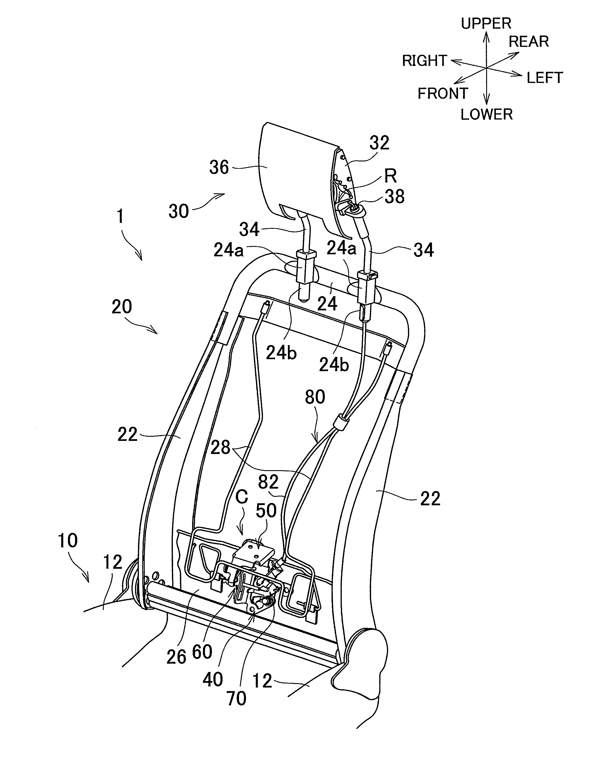
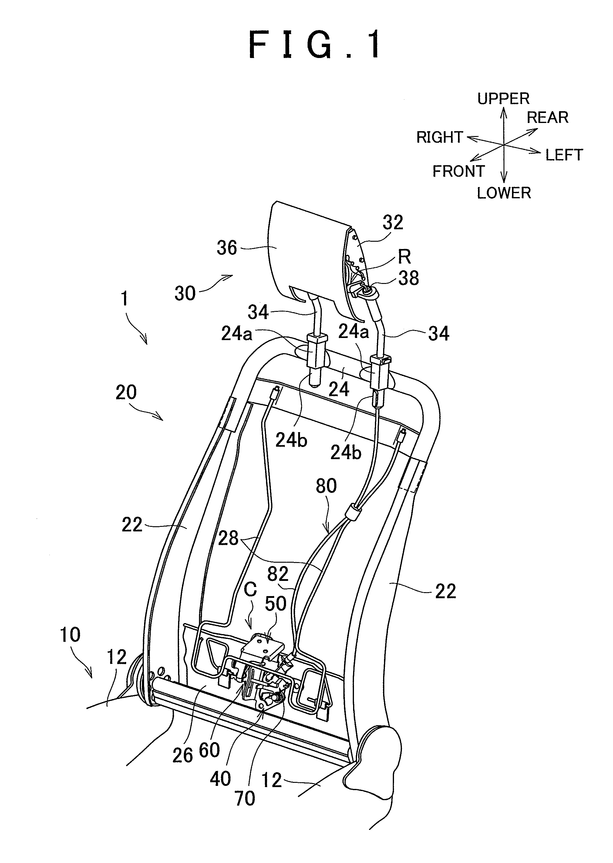
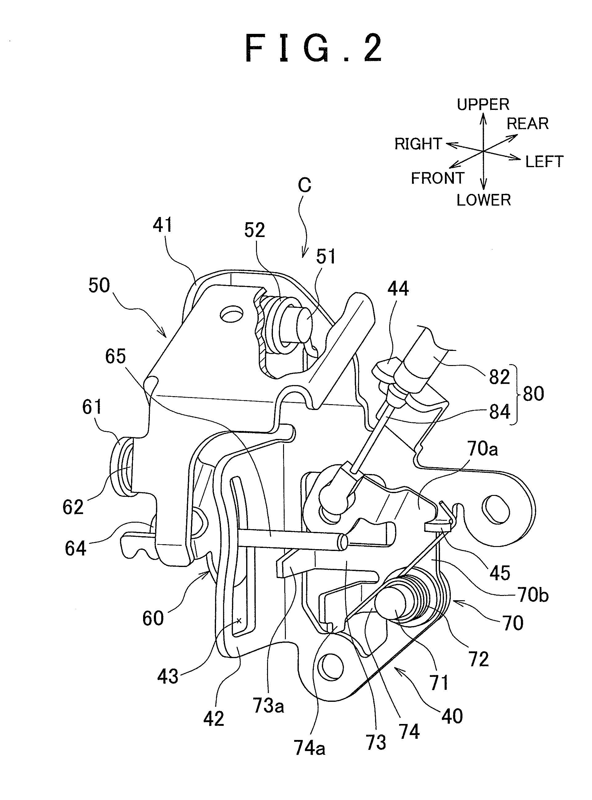
[0028]Hereinafter, an embodiment of the invention will be described with reference to FIG. 1 to FIG. 16. FIG. 1 is an overall schematic view of a vehicle seat to which a clutch mechanism for a vehicle seat is applied according to the embodiment of the invention. FIG. 2 is an enlarged view of the clutch mechanism for a vehicle seat shown in FIG. 1, showing a pressure-receiving member with a portion cut away. FIG. 3 is a front schematic view of FIG. 2. FIG. 4 is a side schematic view of FIG. 2.

[0029]FIG. 5 is a schematic view that shows a state where an occupant's backrest load is applied by mere backrest motion of an occupant having a light weight from the state shown in FIG. 4. FIG. 6 is a schematic view that shows a state where an occupant's backrest load is strongly applied when the occupant gets on or off the vehicle from the state shown in FIG. 5. FIG. 7 is a schematic view that shows a state where an occupant's backrest load is strongly applied when a rear-end collision occurs ...


PUM


Abstract

A coupling arm presses a first or second arm of a swing member, connected to a frame of a seat back, by an occupant's backrest load caused by a rear-end collision of a vehicle to pivotally move the swing member. The first arm receives a first backrest load via the coupling arm and the second arm receives a second backrest load, which is larger than the first backrest load, via the coupling arm. The first and second arms are set so that a maximum pivot amount of the swing member when the first arm is pressed to pivot is equal to a maximum pivot amount of the swing member when the second arm is pressed to pivot.

Description

INCORPORATION BY REFERENCE[0001]The disclosure of Japanese Patent Application No. 2008-314392 filed on Dec. 10, 2008 including the specification, drawings and abstract is incorporated herein by reference in its entirety.BACKGROUND OF THE INVENTION[0002]1. Field of the Invention[0003]The invention relates to a clutch mechanism for a vehicle seat and, more particularly, to a clutch mechanism for a vehicle seat, which transmits an occupant's backrest load caused by a rear-end collision of a vehicle.[0004]2. Description of the Related Art[0005]In an existing art, there has been known a headrest for a vehicle seat, of which a portion (support plate) that supports the back of an occupant's head instantaneously pops up toward the back of the occupant's head in the event of a rear-end collision of a vehicle. Here, Japanese Patent Application Publication No. 2005-95237 (JP-A-2005-95237) describes a technique in which the support portion pops up as described above as a load of an occupant sea...

Claims


Application Information

Patent Timeline
Patent Type & Authority Applications(United States)
IPC IPC(8): B60N2/427B60N2/42
CPCB60N2/4228B60N2/4885B60N2/42781B60N2/888
Inventor OTSUKA, TAIYO
Owner TOYOTA BOSHOKU KK
Why Eureka
Try Eureka