Vibroseis acquisition method

a technology of vibration acquisition and acquisition method, applied in the field of vibration acquisition method, can solve the problems of contaminating preceding sweep records, limiting the distance between these two start times, and unable to eliminate harmonics, so as to enhance the fundamentals of the signal s

a technology of vibration acquisition and acquisition method, applied in the field of vibration acquisition method, can solve the problems of contaminating preceding sweep records, limiting the distance between these two start times, and unable to eliminate harmonics, so as to enhance the fundamentals of the signal s

US20100142320A1Active Publication Date: 2010-06-10WESTERNGECO LLC

Image

  • Vibroseis acquisition method
  • Vibroseis acquisition method
  • Vibroseis acquisition method

Examples


Embodiment Construction

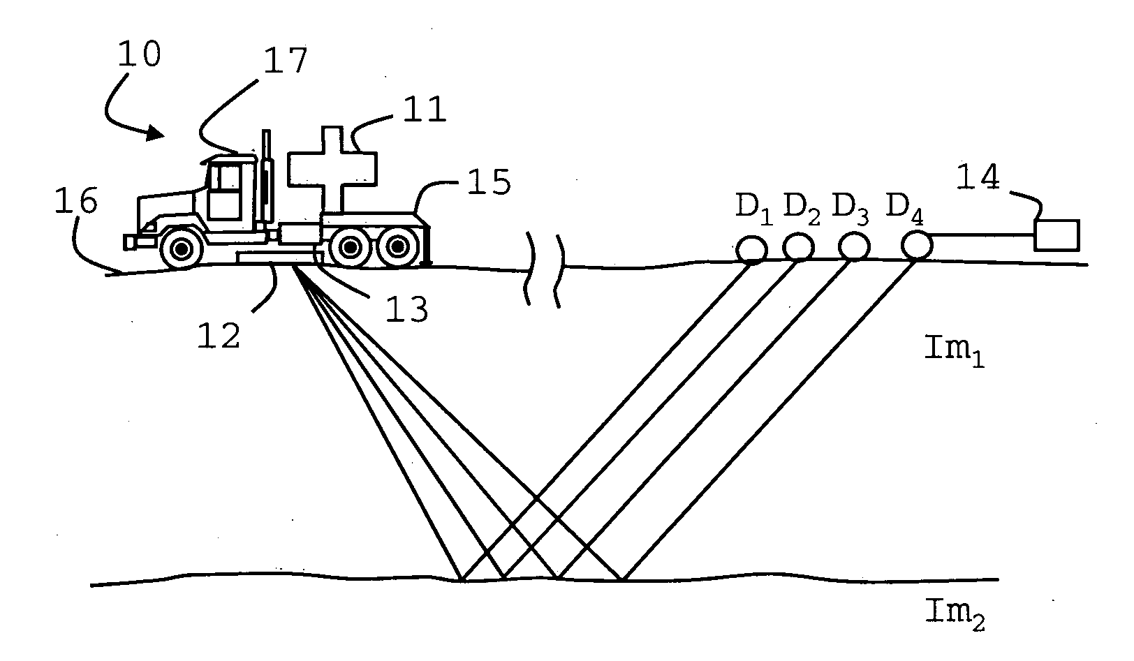
[0029]The system of FIG. 1 illustrates in a simplified manner the elements of a Vibroseis acquisition system, such as may be used in embodiments of the present invention. In the illustrated system, a seismic vibrator 10 comprises a vibrating element or reaction mass 11, a baseplate 12 and a signal measuring apparatus 13, for example a plurality of accelerometers whose signals are combined to measure the actual ground-force signal applied to the earth by the seismic vibrator. The seismic vibrator 10 illustrated in FIG. 1 is constructed on a truck 17 that provides for maneuverability of the system. As illustrated, the reaction mass 11 is coupled with the baseplate 12 to provide for the transmission of vibrations from the vibrating element 11 to the baseplate 12. The baseplate 12 is positioned in contact with an earth surface 16 such that the vibrations of the vibrator 11 are communicated into the earth surface 16.

[0030]The seismic signal that is generated by the reaction mass 11 and e...


PUM


Abstract

A method of performing a Vibroseis survey is described including the step of obtaining signals generated by activating vibratory sources at times T0 and T1, respectively, for a sweep period S and a listening time L such that T1<T0,S+L, wherein harmonic noise within the signals are attenuated using a first method to estimate the harmonics in a time-frequency interval in which harmonics of the sweep T1 overlap with the response to the fundamental of sweep T1 and using a second method for estimating the harmonics in a time-frequency with no overlap.

Description

[0001]The present invention relates to a method of improving Vibroseis acquisition based on the slip-sweep method.BACKGROUND OF THE INVENTION[0002]Vibroseis acquisition is based on activation of one or more Vibroseis sources. The Vibroseis sources are vibrators designed to emit a signal of varying frequency into the ground. The signal is usually referred to as “sweep” with signal starting at the low frequency are up-sweeps and those starting at the high frequency are down-sweeps.[0003]In a seismic acquisition, single or groups of vibrators are activated in sequence. The time lag between the start of the sweep of the previous group and the start of the sweep of the subsequent group is a critical parameter. The closer the starts the more efficient use can be made of the vibrator equipment in the field. However there are limits as to how close these two start times can be, before signal caused by the second groups leaks into the recordings relating to the sweep of the first group.[0004...

Claims


Application Information

Patent Timeline
10 Jun 2010
Publication
US20100142320A1
IPC
G01V1/37
CPC
G01V1/37; G01V2210/34; G01V1/28; G01V1/005
Inventors
BAGAINI, CLAUDIO