Super-frame structure for dynamic spectrum sharing in wireless networks

a wireless network and superframe technology, applied in the field of wireless systems, can solve the problems of significant economic pressure to efficiently use the spectrum, difficulty in sharing spectrum, and currently not being used efficiently

a wireless network and superframe technology, applied in the field of wireless systems, can solve the problems of significant economic pressure to efficiently use the spectrum, difficulty in sharing spectrum, and currently not being used efficiently

US20100142559A1Active Publication Date: 2010-06-10STMICROELECTRONICS SRL

Image

  • Super-frame structure for dynamic spectrum sharing in wireless networks
  • Super-frame structure for dynamic spectrum sharing in wireless networks
  • Super-frame structure for dynamic spectrum sharing in wireless networks

Examples


Embodiment Construction

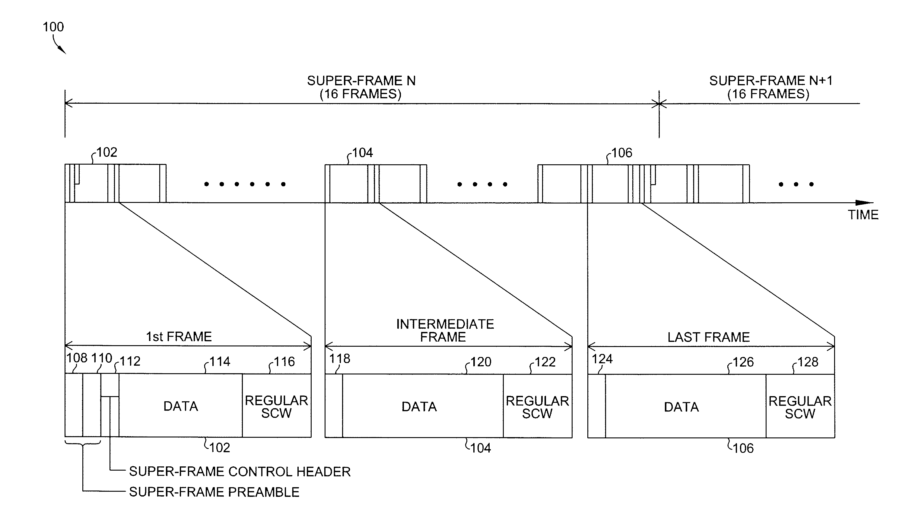
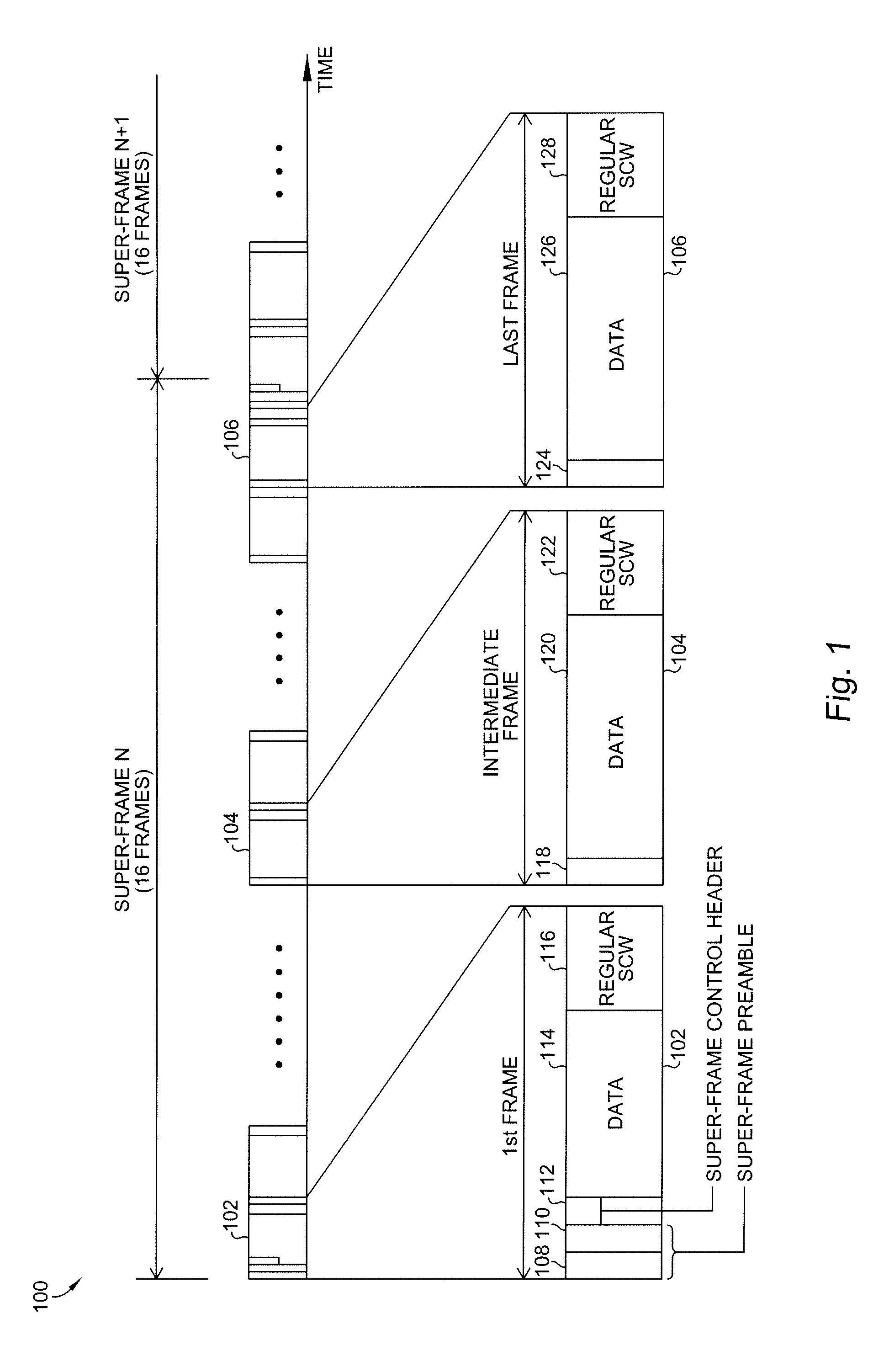
[0013]Referring now to FIG. 1, a super-frame structure 100 is shown in the time domain according to an embodiment of the present invention. The purpose of the super-frame structure is to allow dynamic spectrum sharing between wireless systems that are operating in the same proximity and have overlapping coverage areas. The super-frame structure allows negotiation and coordination between wireless systems regarding the specifics of spectrum sharing, and the announcement of those negotiations so that other unlicensed systems in the coverage area can be notified.

[0014]The super-frame structure 100 of the present invention includes, for example, sixteen frames including a first frame 102, an intermediate frame 104, and a last frame 106. Although sixteen frames are shown in FIG. 1, the principle of the present invention is not obviated by using a different number of frames. The first frame includes a super-frame preamble including two OFDM symbols 108 and 110. The use of two OFDM symbols...


PUM


Abstract

A coexistence communications method for use between wireless networks includes adopting a super-frame structure for use in a wireless network having a plurality of frames, wherein a first frame includes a super-frame preamble, a super-frame control header, a data portion, and a regular self-coexistence window, an intermediate frame includes an OFDM symbol, a data portion, and a regular self-coexistence window, and a last frame includes an OFDM symbol, a data portion, and a joining self-coexistence window, using the self-coexistence windows to exchange inter-wireless network co-existence messages, and using a last reserved self-coexistence window to announce intra-wireless network negotiation decisions.

Description

CROSS REFERENCE TO PRIORITY AND RELATED PATENT APPLICATION[0001]This application claims the benefit of U.S. Provisional Patent Application No. 61 / 120,256, filed on Dec. 5, 2008, which is hereby incorporated by reference for all purposes as if fully set forth herein.[0002]The present invention is also related to the subject matter disclosed in U.S. patent application Ser. No. ______ filed on DDMMYY for: “FRAME-BASED ON-DEMAND SPECTRUM CONTENTION PROTOCOL-MESSAGING METHOD”, assigned to the assignee of the present invention, the disclosure of which is herein specifically incorporated by this reference in its entirety.BACKGROUND OF THE INVENTION[0003]The present invention relates to wireless systems and, more specifically to an super-frame structure that allows efficient spectrum sharing and cross-channel inter-cell communications for IEEE 802.22 systems.[0004]In recent years wireless systems have been proliferating. Wireless networks share a scarce resource, the electromagnetic spectru...

Claims


Application Information

Patent Timeline
10 Jun 2010
Publication
US20100142559A1
IPC
H04J3/24
CPC
H04L5/0053; H04L27/2602; H04W92/02; H04W16/14; H04W48/10; H04W8/005
Inventors
HU, WENDONG