

Bi-directional video compression for real-time video streams during transport in a packet switched network
a packet switched network and video compression technology, applied in the field of packet switched networks, can solve the problems of inability of mpeg compression coders/decoders (codecs) to look ahead to make coding decisions, and the inability of b-vop/b-frames to be used in real-time video transports without introducing delays, so as to improve compression efficiency
- Summary
- Abstract
- Description
- Claims
- Application Information
AI Technical Summary
Benefits of technology
Problems solved by technology
Method used
Image

Examples
Embodiment Construction
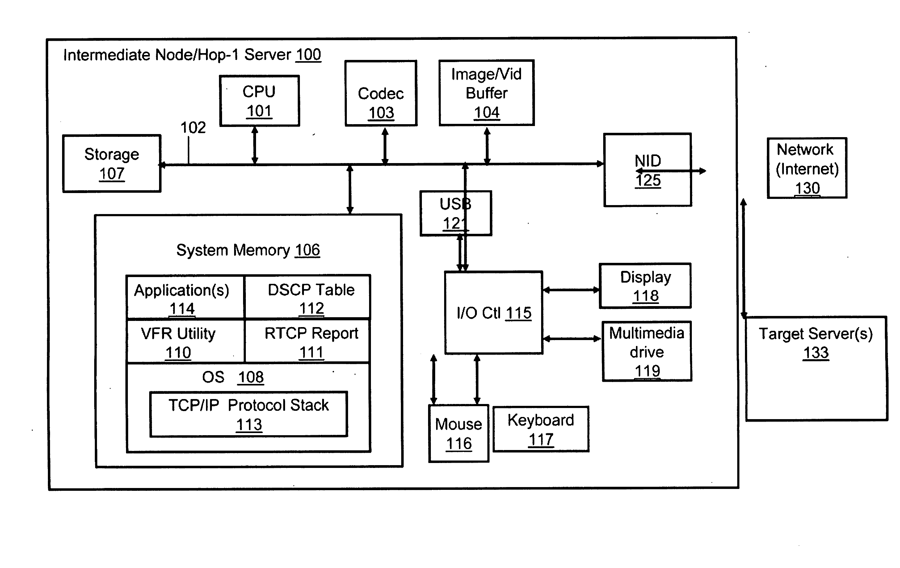
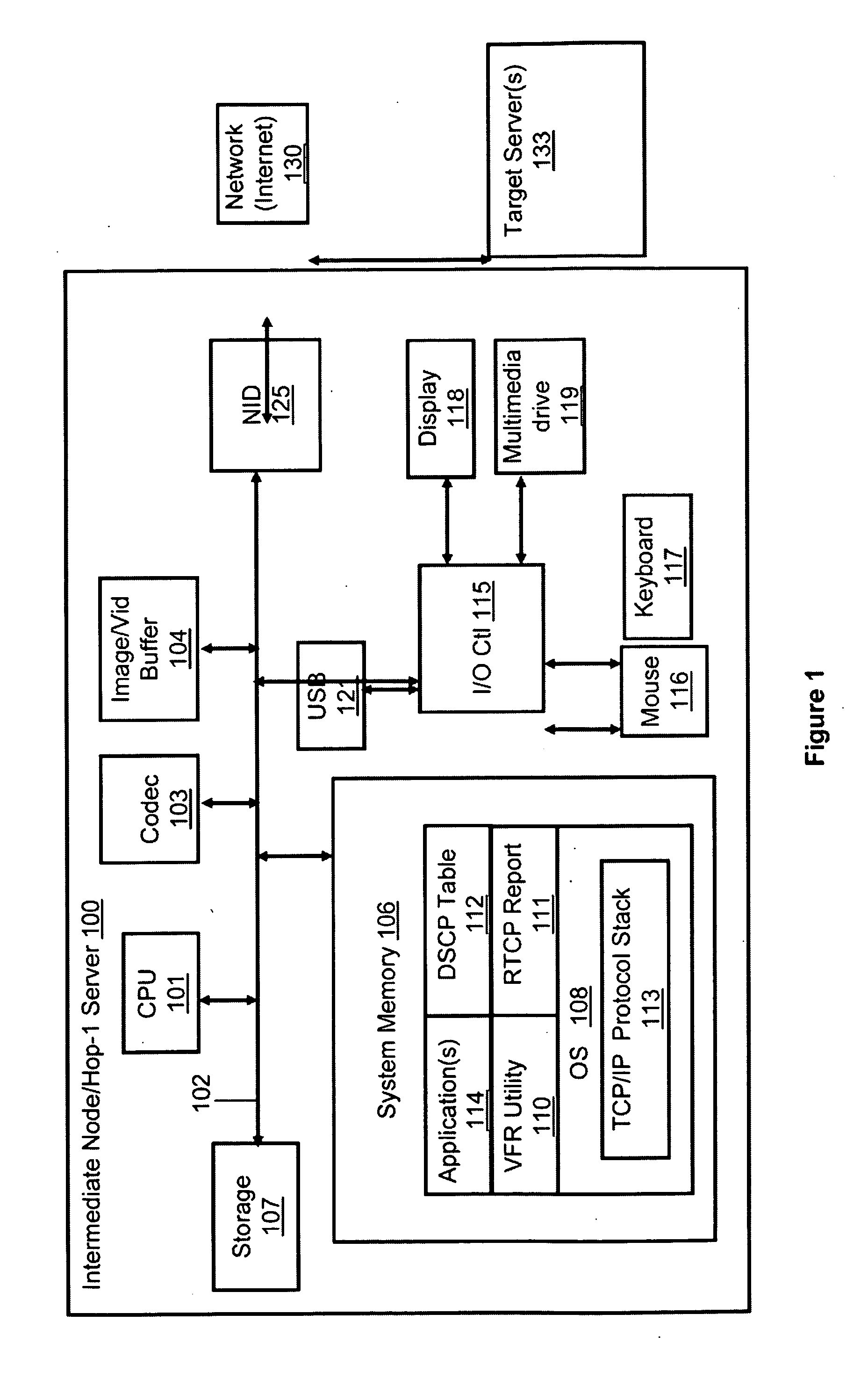
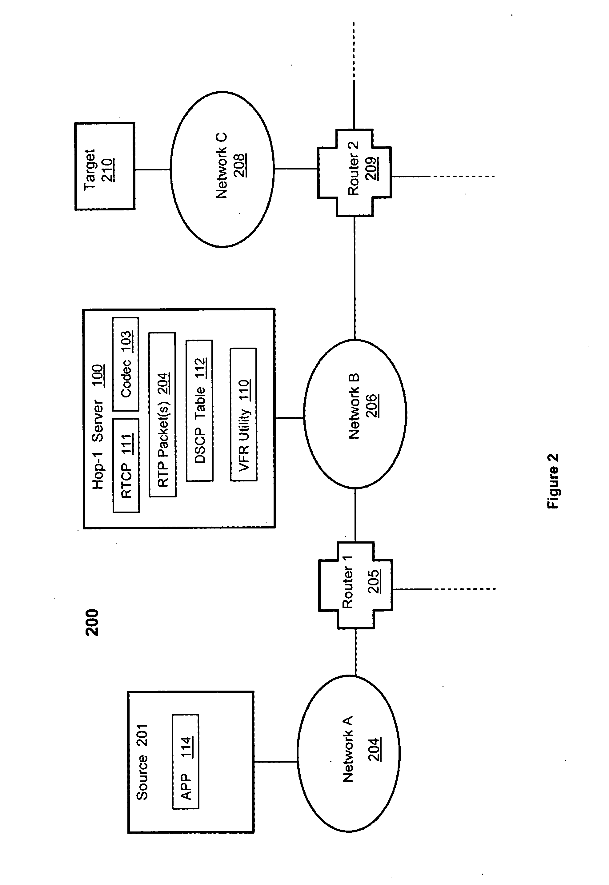
[0006]Disclosed are a method, a system and a computer device for initiating bi-directional compression of a video stream in a packet switched network, based on delay tolerance of a service or application. A video frame recompression (VFR) utility determines an end-to-end (E2E) delay tolerance retrieved from a Real-time Transport Control Protocol (RTCP) report. The VFR utility then determines the actual expected delay based on a deep inspection of packet headers. The VFR utility utilizes a processing opportunity delay (which determines whether the E2E delay tolerance is greater than the actual expected delay) to reprocess video content comprising Intra-coded (I) pictures / frames and Predicted (P) frames to improve compression efficiency. The VFR utility may also utilize a complexity ratio, determined as a ratio of the I-Frame rate and the P-Frame rate, to select frames for compression. The VFR utility recompresses video content by replacing P-Frames with Bi-predictive (B-) Frames.
[000...
PUM
 Abstract
Description
Claims
Application Information