Microfluidic device

Inactive Publication Date: 2010-06-10
ELECTRONICS & TELECOMM RES INST
View PDF6 Cites 68 Cited by
  • Summary
  • Abstract
  • Description
  • Claims
  • Application Information

AI Technical Summary

Benefits of technology

[0005]The present invention provides a microfluidic device that can p

Problems solved by technology

However, typical microfluidic devices require a large amount of sample fluid

Method used


Image

  • Microfluidic device
  • Microfluidic device
  • Microfluidic device

Examples


Example

[0024]Preferred embodiments of the present invention will be described below in more detail with reference to the accompanying drawings. The present invention may, however, be embodied in different forms and should not be construed as limited to the embodiments set forth herein. Rather, these embodiments are provided so that this disclosure will be thorough and complete, and will fully convey the scope of the present invention to those skilled in the art.

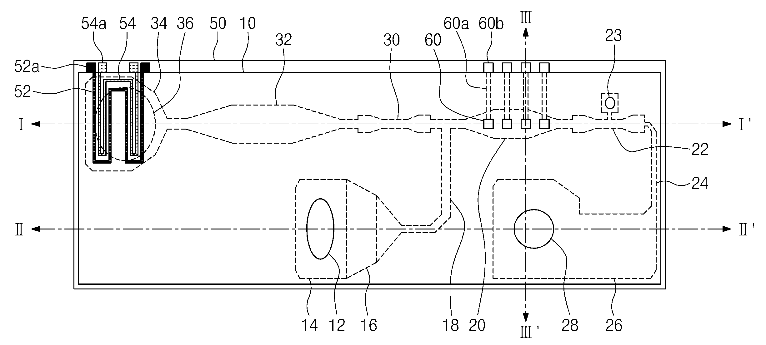
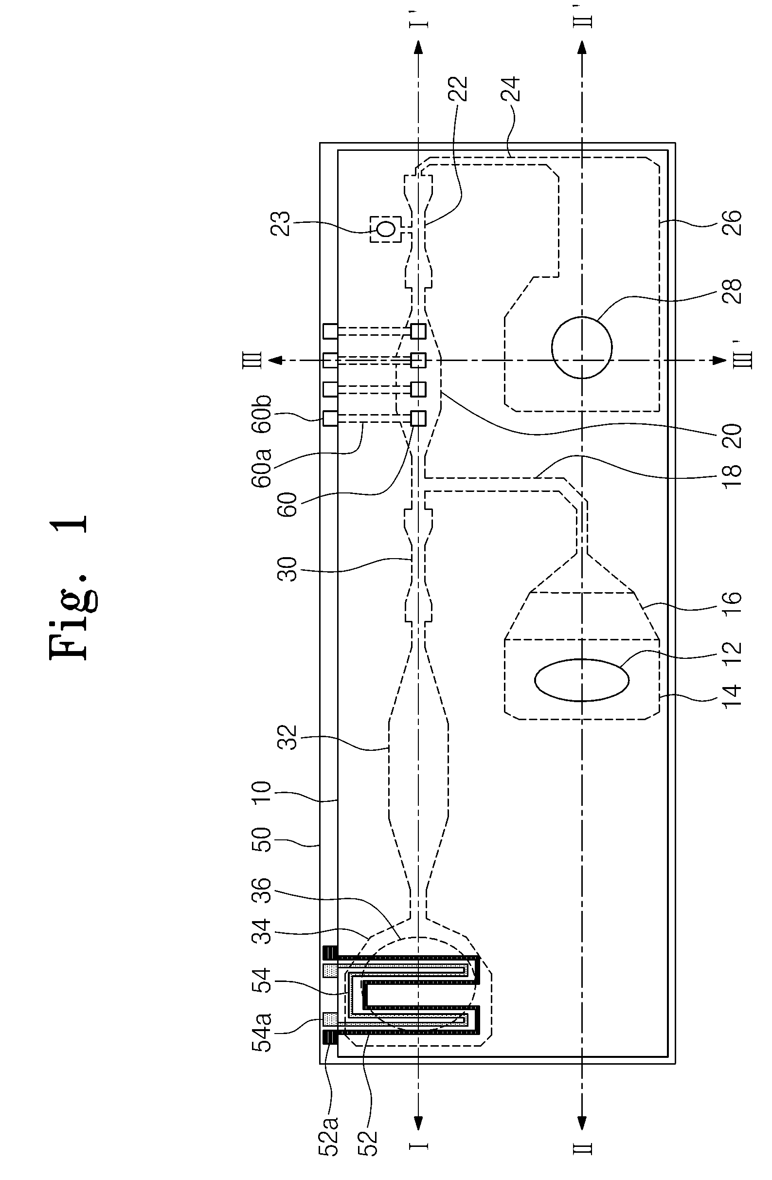
[0025]FIG. 1 is a top plan view of a microfluidic device according to an embodiment of the present invention, FIG. 2A is a top plan view of a lower plate of FIG. 1, FIG. 2B is a top plan view of an upper plate of FIG. 1, FIG. 3 is a cross-sectional view taken along line I-I′ of FIG. 1, FIG. 4A is a cross-sectional view taken along line II-II′ of FIG. 1 according to one embodiment, FIG. 4B is a cross-sectional view taken along line II-II′ of FIG. 1 according to another embodiment, and FIG. 5A is a cross-sectional view taken along lin...


PUM


Abstract

Provided is a microfluidic device. The microfluidic device includes a sample storage chamber storing sample fluid therein, a detection chamber connected to the sample storage chamber and detecting a specific material of the sample fluid, a cleaning liquid storage chamber connected to the detection chamber and storing cleaning liquid therein, a plurality of fluid passages interconnecting the chambers, and a micropump transferring the cleaning liquid. The microfluidic device precisely inspects a sample fluid although a small amount of the sample fluid flows.

Description

CROSS-REFERENCE TO RELATED APPLICATIONS[0001]This U.S. non-provisional patent application claims priority under 35 U.S.C. §119 of Korean Patent Application No. 10-2008-0124028, filed on Dec. 8, 2008, and Korean Patent Application No. 10-2009-0026261, filed on Mar. 27, 2009, the entire contents of which are hereby incorporated by reference.BACKGROUND OF THE INVENTION[0002]The present invention disclosed herein relates to a microfluidic device.[0003]Microfluidic devices are variously applied to lab-on-a-chips such as protein chips, DNA chips, drug delivery systems, micro total analysis systems, and micro reactors that require precise and fine fluid controlling.[0004]Typical microfluidic devices utilize flow of fluid based on capillary force. It is important for a microfluidic device to control the flow rate of a sample fluid for improving the sensitivity of the microfluidic device to a particular substance included in the sample fluid. To this end, a variety of methods have been resea...

Claims


Application Information

Patent Timeline
IPC IPC(8): B01J19/00
CPCB01L3/50273B01L9/52B01L2300/0681B01L2300/0816F04B19/006B01L2400/0406B01L2400/046B01L2400/0677B01L2300/1827B01L13/02
Inventor LEE, DAE-SIKCHOI, YO HANCHUNG, KWANG HYOJEON, JUHYUNSONG, HYUN WOOJUNG, MOON YOUNPARK, SEON HEE
Owner ELECTRONICS & TELECOMM RES INST
Why Eureka
Try Eureka