
Load frequency response test system and method for hydraulic cylinder

A frequency response test, frequency response technology, applied in fluid pressure actuation system test, machine/structural component test, measurement device and other directions, can solve the problem of test result influence, failure to achieve the test purpose, etc., and achieve a high degree of automation , The effect of accurate test and simple system structure

Inactive Publication Date: 2009-06-24
WUHAN UNIV OF SCI & TECH
View PDF0 Cites 34 Cited by
  • Summary
  • Abstract
  • Description
  • Claims
  • Application Information

AI Technical Summary

Problems solved by technology

The problem with the above test method: the frequency response index of the tested servo hydraulic cylinder includes the frequency response index of the hydraulic cylinder loaded in the closed frame
That is, if the frequency response index of the loaded hydraulic cylinder is higher than that of the tested servo hydraulic cylinder, it has little effect on the test results; if the frequency response index of the loaded servo hydraulic cylinder is lower than the frequency response index of the tested servo hydraulic cylinder , the test result can only reflect the frequency response index of the loaded hydraulic cylinder, thus failing to achieve the test purpose (Edited by Wang Chunxing, Hydraulic Control System, Beijing: Machinery Industry Press, 2007.pp49)

Method used


Image

  • Load frequency response test system and method for hydraulic cylinder
  • Load frequency response test system and method for hydraulic cylinder
  • Load frequency response test system and method for hydraulic cylinder

Examples


Embodiment Construction

[0038] The present invention will be further described below in conjunction with accompanying drawing and specific embodiment, not limitation to protection scope:

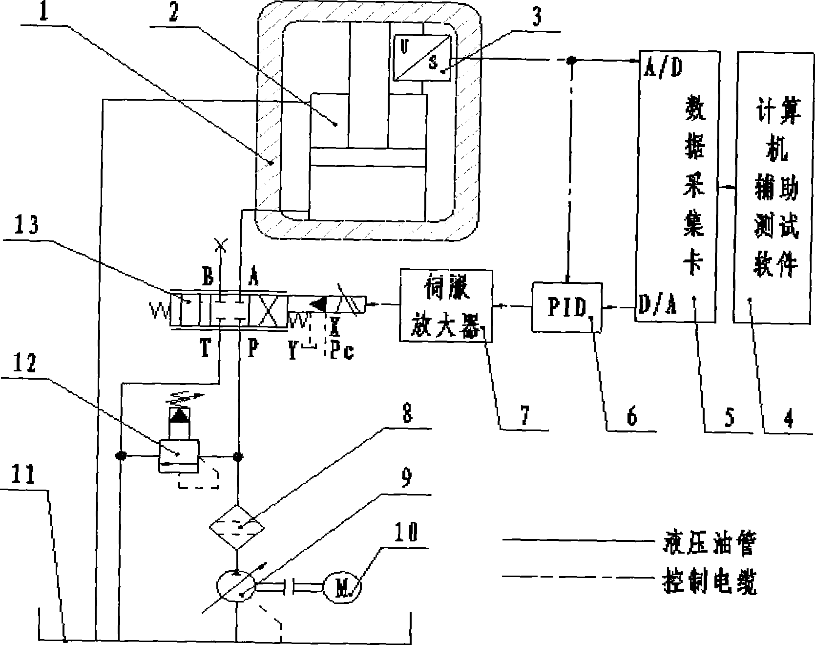
[0039] A test system and test method for measuring the load frequency response of a hydraulic cylinder, the test system is as follows figure 1 As shown: the oil pump 9 is coaxially connected with the motor 10, the oil suction port of the oil pump 9 communicates with the oil tank 11, the oil outlet port of the oil pump 9 communicates with the P port of the electro-hydraulic servo valve 13 through the filter 8, and the A port of the electro-hydraulic servo valve 13 The port communicates with the rodless chamber of the tested hydraulic cylinder 2, and the B port of the electro-hydraulic servo valve 13 is closed; the rod chamber of the tested hydraulic cylinder 2 and the T port of the electro-hydraulic servo valve 13 communicate with the oil tank 11; An electromagnetic overflow valve 12 is connected between the P port ...


PUM


Abstract

The invention relates to a load frequency response test system of a hydraulic cylinder and a test method thereof. The technical scheme of the system is as follows: the oil outlet of an oil pump (9) is communicated with the port P of an electro hydraulic servovalve (13), wherein, the opening A or the port B of the electro hydraulic servovalve (13) is communicated with the rodless chamber of a hydraulic cylinder (2) to be tested, and the rod chamber of the hydraulic cylinder (2) to be tested is communicated with an oil tank (11); the hydraulic cylinder (2) to be tested is installed in a closed stander (1); a displacement sensor (3) is installed on the hydraulic cylinder (2) to be tested and is electrically connected with the A / D port of a data collecting card (5) and a PID controller (6); and one end of a servoamplifier (7) is electrically connected with an electromagnet of the electro hydraulic servovalve (13), the other end of the servoamplifier (7) is electrically connected with one end of the PID controller (6), the other end of the PID controller (6) is electrically connected with the D / A port of the data collecting card (5), and the data collecting card (5) and computer-aided test software (4) are installed in a computer. The load frequency response test system has the advantages of simple systematic structure, accurate test and high degree of automation.

Description

technical field [0001] The invention belongs to the technical field of hydraulic component testing. In particular, it relates to a hydraulic cylinder load frequency response testing system and testing method. Background technique [0002] The hydraulic system is widely used in important parts of metallurgical production equipment due to its advantages of high power, fast response and high precision. The hydraulic cylinder is the actuator of the hydraulic system, and its response speed during the load movement has a great influence on the performance of the entire hydraulic system. Therefore, it is very necessary to accurately test the load frequency response characteristics of the hydraulic cylinder. Especially servo hydraulic cylinders for crystallizer vibration, rolling mill hydraulic pressure (AGC) servo hydraulic cylinders, alternating loading hydraulic cylinders for automotive road spectrum fatigue testing machines, etc., which require high response speed, must respond...

Claims


Application Information

Patent Timeline
IPC IPC(8): F15B19/00F15B15/00G01M19/00G01M99/00
Inventor 陈新元陈奎生曾良才付连东湛从昌黄富瑄梁媛媛张济民卢云丹
Owner WUHAN UNIV OF SCI & TECH
Learn More