
Probe device

Active Publication Date: 2016-02-18
TOKYO ELECTRON LTD
View PDF3 Cites 2 Cited by
  • Summary
  • Abstract
  • Description
  • Claims
  • Application Information

AI Technical Summary

Benefits of technology

The invention enables accurate testing without causing twisting or damage to the mounting table.

Problems solved by technology

), the mounting table may be warped due to difference in thermal expansion coefficients of the insulating layer and the conductive layers, thereby making it difficult to bring the probe into accurate contact with an electrode of the semiconductor device.
Further, due to the difference in thermal expansion coefficients of the insulating layer and the conductive layers, the conductive layers may be detached from the insulating layer and thus the mounting table may be damaged.
Furthermore, due to the difference in thermal expansion coefficients of the insulating layer and the conductive layers, stress may be applied to the insulating layer to have a crack in the insulating layer and thus the mounting table may be damaged.

Method used


Image

  • Probe device
  • Probe device
  • Probe device

Examples


Embodiment Construction

[0016]Hereinafter, embodiments of the present invention will be described in detail with respect to the accompanying drawings.

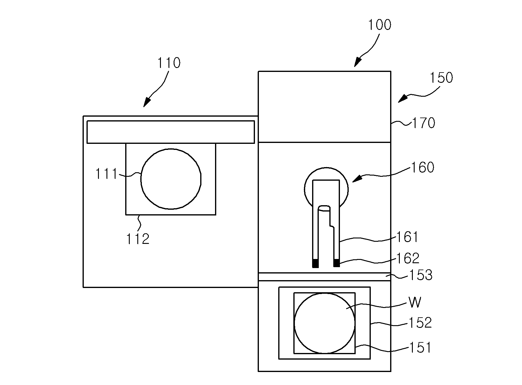
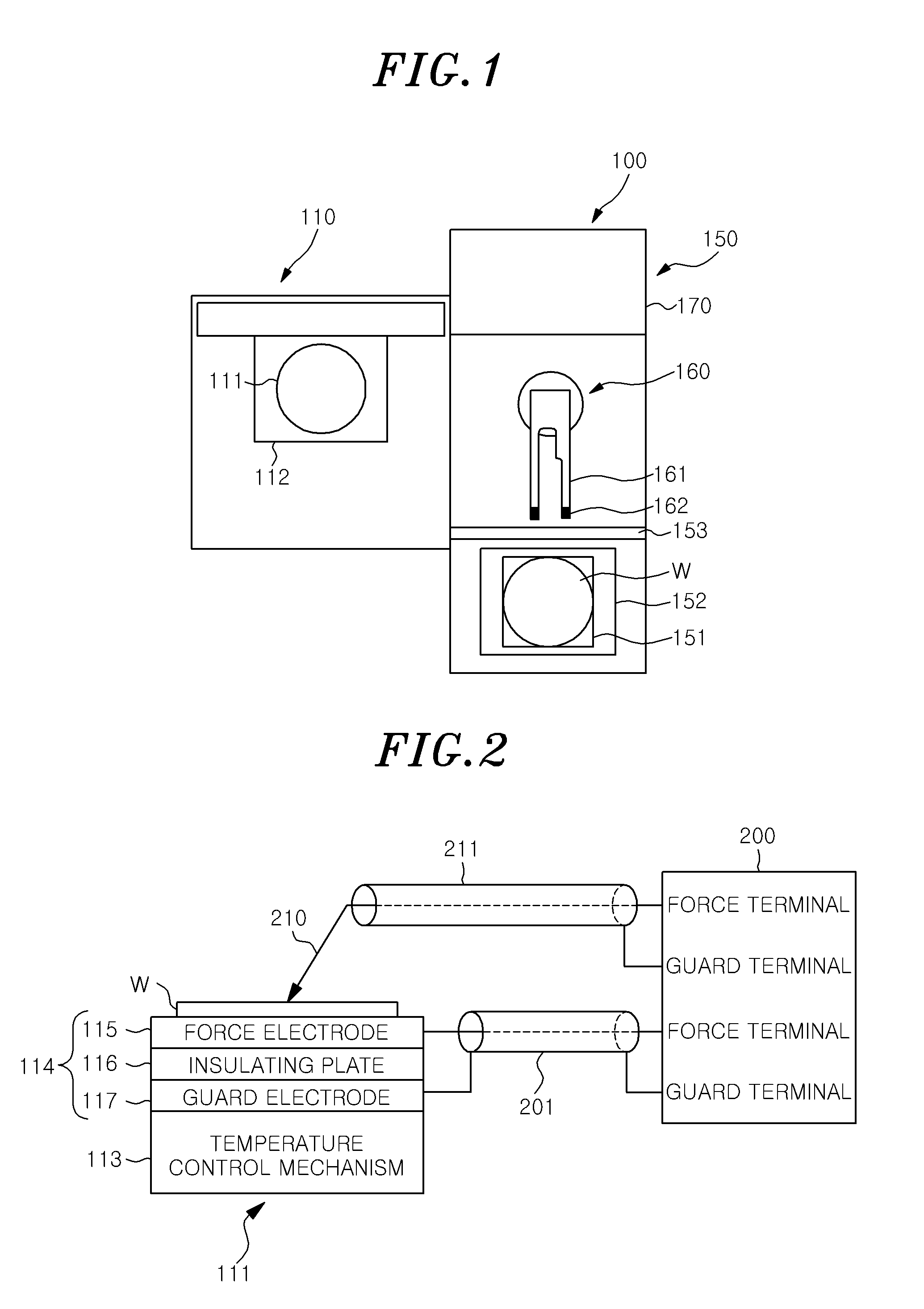
[0017]FIG. 1 is a plan view schematically showing an entire configuration of a probe device 100 in accordance with an embodiment of the present invention. The probe device 100 of FIG. 1 includes a measuring unit 110 and a loader unit 150 serving as a transfer unit. The measuring unit 110 is movable in x-y-z-θ directions, and includes a circular disk-shaped mounting table 111 on which a semiconductor wafer W is mounted. By driving the mounting table 111 by a driving mechanism 112, the measuring unit 110 makes probes 210 (see FIG. 2) provided at a probe card and electrodes of semiconductor devices formed on the semiconductor wafer W contact with each other to measure electrical characteristics of the semiconductor devices.

[0018]The loader unit 150 includes a load port 152 on which a wafer carrier (wafer cassette or FOUP) 151, which accommodates the semiconducto...


PUM


Abstract

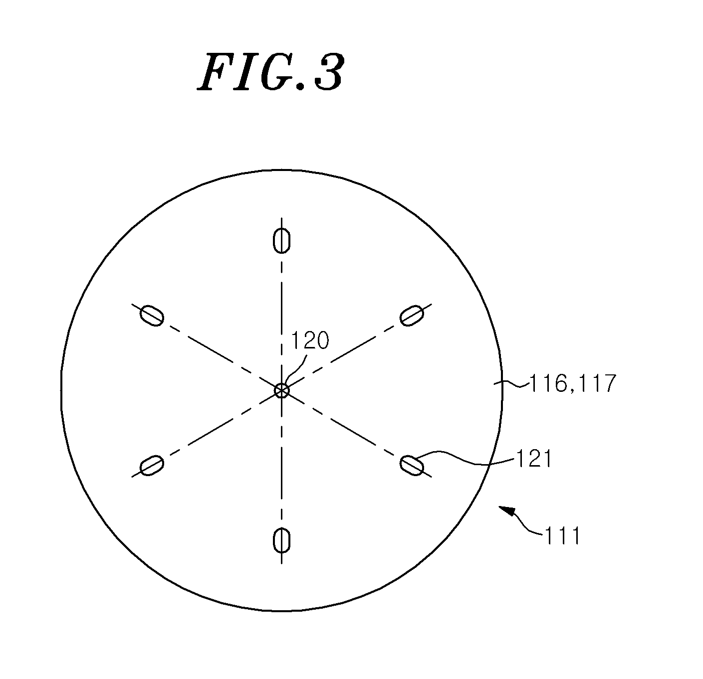
A probe device, for performing an electrical test of a semiconductor device formed on a semiconductor wafer, includes a mounting table on which the semiconductor wafer is mounted, a driving mechanism configured to bring a probe into contact with an electrode of the semiconductor device mounted on the mounting table, and a temperature control mechanism configured to control a temperature of the mounting table. The mounting table includes a disk-shaped first electrode, a disk-shaped second electrode, and a disk-shaped insulating plate interposed between the first electrode and the second electrode. The first electrode, the second electrode and the insulating plate are fixed to each other at a fixing part provided at their respective centers, and are locked to be movable in a diametric direction at a locking part provided at an outer side of the fixing part in the diametric direction.

Description

CROSS REFERENCE[0001]This application is a National Stage Application of, and claims priority to, PCT Application No. PCT / JP2014 / 058149, filed on Mar. 18, 2014, entitled “Probe Device,” which claims priority to Japanese Patent Application No. 2013-065510, filed on Mar. 27, 2013. The foregoing patent applications are herein incorporated by reference by entirty for all purposes.FIELD OF THE INVENTION[0002]The present invention relates to a probe device.BACKGROUND OF THE INVENTION[0003]In a manufacturing process of a semiconductor device, a probe device is used to perform an electrical test of a semiconductor device formed on a semiconductor wafer. The probe device drives a mounting table on which the semiconductor wafer is mounted and makes a probe contact with an electrode of the semiconductor device formed on the semiconductor wafer to thereby obtain electrical conduction. The test of the semiconductor device is performed by detecting an output signal from the semiconductor device t...

Claims


Application Information

Patent Timeline
IPC IPC(8): G01R31/28
CPCG01R31/2891G01R31/2874G01R1/18G01R31/2865
Inventor HATTA, MASATAKA
Owner TOKYO ELECTRON LTD
Learn More