Anti-Spill Urinal

Inactive Publication Date: 2010-06-10
MATHEWS J L JOSEPH L
View PDF17 Cites 2 Cited by
  • Summary
  • Abstract
  • Description
  • Claims
  • Application Information

AI Technical Summary

Problems solved by technology

The insertion of the Foley catheter may be uncomfortable for the pa

Method used


Image

  • Anti-Spill Urinal
  • Anti-Spill Urinal

Examples


Embodiment Construction

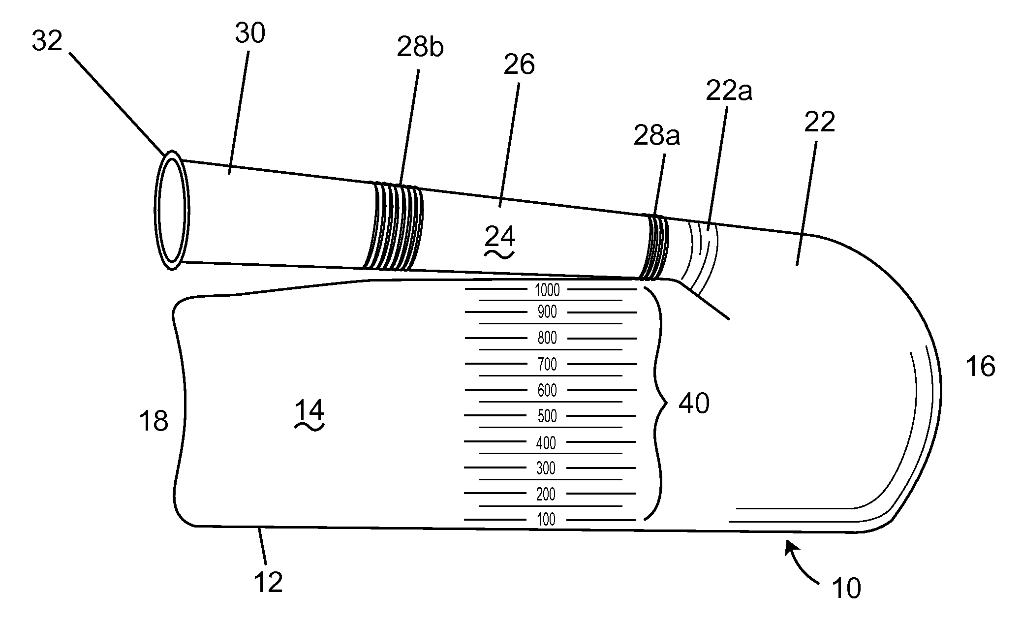
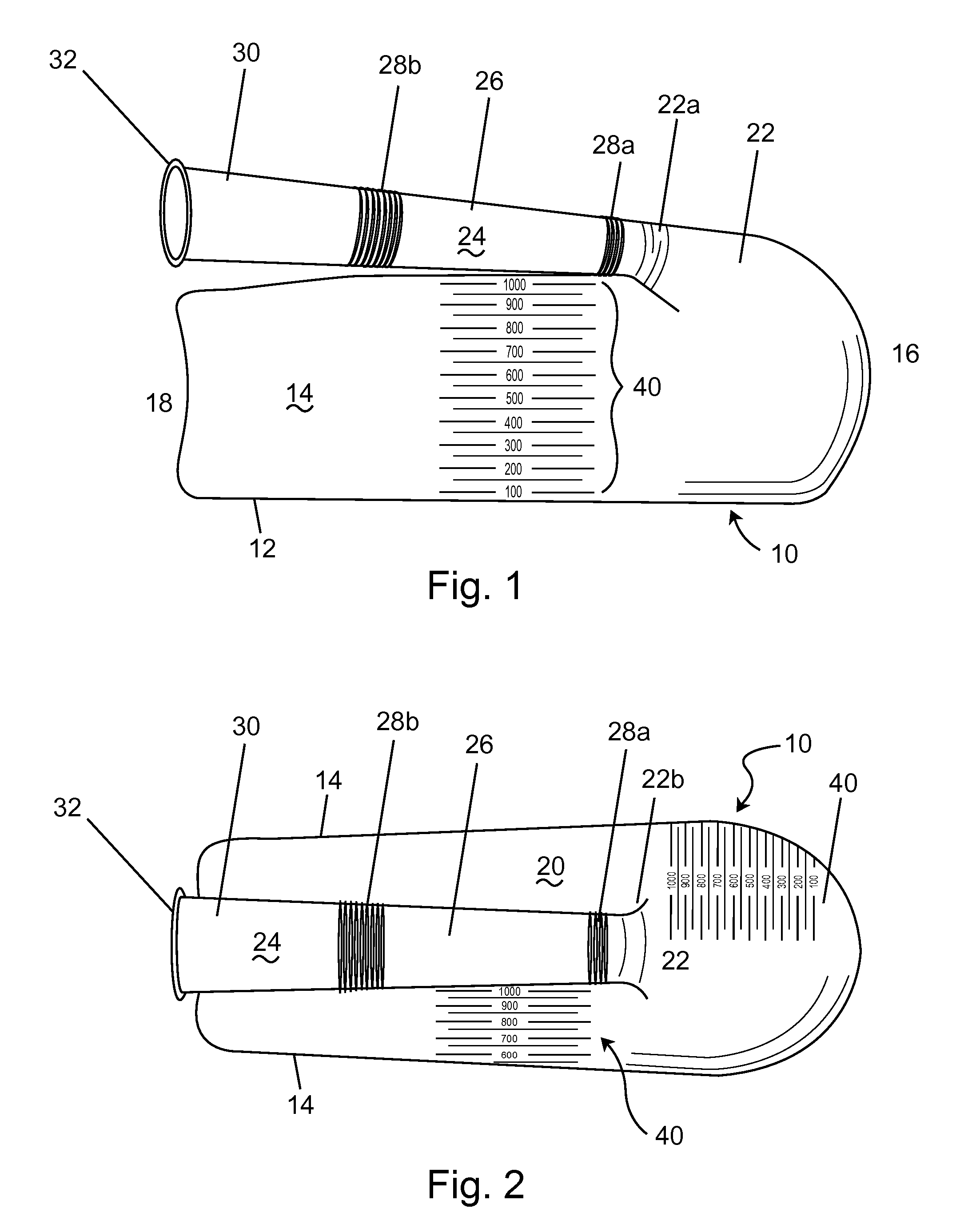
[0012]FIG. 1 and FIG. 2 illustrate a blow-molded plastic urinal having vessel 10 formed of a base 12, and sidewalls 14, 16 and 18 and a top wall 20. The sidewalls may be curved to conform to the inner thighs of the patient to improve comfort. The vessel 10 may also be tapered, that is wall 16 may be longer than wall 18 of the vessel to have a generally trapezoidal shape, again to allow the vessel 10 to fit between the patient's thighs.

[0013]The vessel 10 includes a finish 22 formed into one or more of the sidewalls 14, 16 or 18 and the top wall 20. The finish 22 is suited to receiving a flexible tube 24 and may include a series of threads 22a (shown in FIG. 1), for a threaded connection to the tube 24, or a relatively flat surface 22b (shown in FIG. 2), for a friction-fit connection to the tube 24. The vessel 10 may optionally include graduation marks 40 on a sidewall of the vessel and may include a second set of graduation marks at an angle orthogonal to marks 40 so that the volume...


PUM


Abstract

The present invention relates to urinals for use by the bedridden. The anti-spill urinal of the present invention includes a flexible tube for improved contact with the patient. The present invention may also include a rounded lip for improved contact with the patient. The urinal of the present invention may include a substantially closed vessel having a bottom wall, side walls, and a top wall with an opening in the top wall of the vessel in combination with a tube in fluid connection with the opening. Preferably, the tube has a number of flexible sections, separated by a number of rigid sections to increase patient comfort and reduce spills. The present invention may also include an extensible section at the distal end of the tube and a graduated section formed in a sidewall of the vessel for measuring the volume of fluid within the vessel.

Description

TECHNICAL FIELD AND INDUSTRIAL APPLICABILITY OF THE INVENTION[0001]The present invention relates to portable urine collection devices, typically referred to as urinals.BACKGROUND OF THE INVENTION[0002]Hospital patients and residents of nursing home with difficulty moving from a bed are often fitted with a Foley catheter. The Foley catheter is a thin, sterile tube inserted into the bladder to drain urine. The insertion of the Foley catheter may be uncomfortable for the patient and may lead to an increase risk of urinary tract infections. The Foley catheter is used because there are no other clean and leak-proof devices for collecting urine.[0003]Currently available urinals rely on a large opening with a cap to seal the urinal after use. One example is U.S. Pat. No. 6,119,280 to Rentsch, issued Sep. 19, 2000 and entitled “All Plastic Leak-Proof Urinal.” The '280 patent recites: The cap has a flat disk-like diaphragm with a reinforced area in the middle thereof. When the cap is placed ...

Claims


Application Information

Patent Timeline
IPC IPC(8): A61M1/00A61M31/00
CPCA61J2200/76A61G9/006
Inventor MATHEWS, J.L., JOSEPH L.
Owner MATHEWS J L JOSEPH L
Why Eureka
Try Eureka