Engine using bouyant elements

a technology of bouyant elements and engines, applied in the field of engines, to achieve the effect of greater rotational torqu

Inactive Publication Date: 2010-06-17
SILVA THOMAS A
View PDF16 Cites 24 Cited by
  • Summary
  • Abstract
  • Description
  • Claims
  • Application Information

AI Technical Summary

Problems solved by technology

The engine is designed to rotate as a result of an imbalance in the buoyant forces created by the various float members.

Method used


Image

  • Engine using bouyant elements
  • Engine using bouyant elements
  • Engine using bouyant elements

Examples


Embodiment Construction

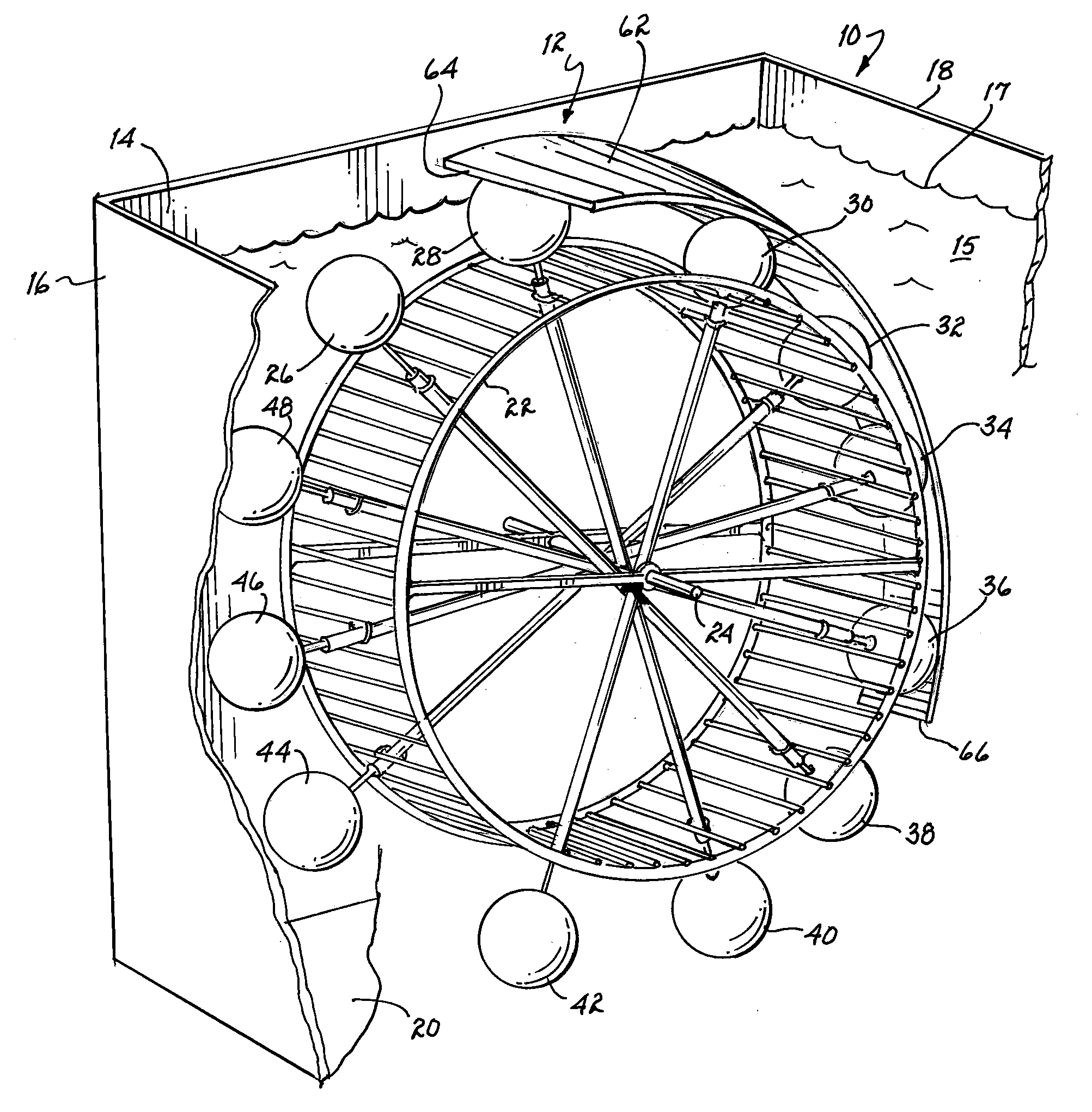
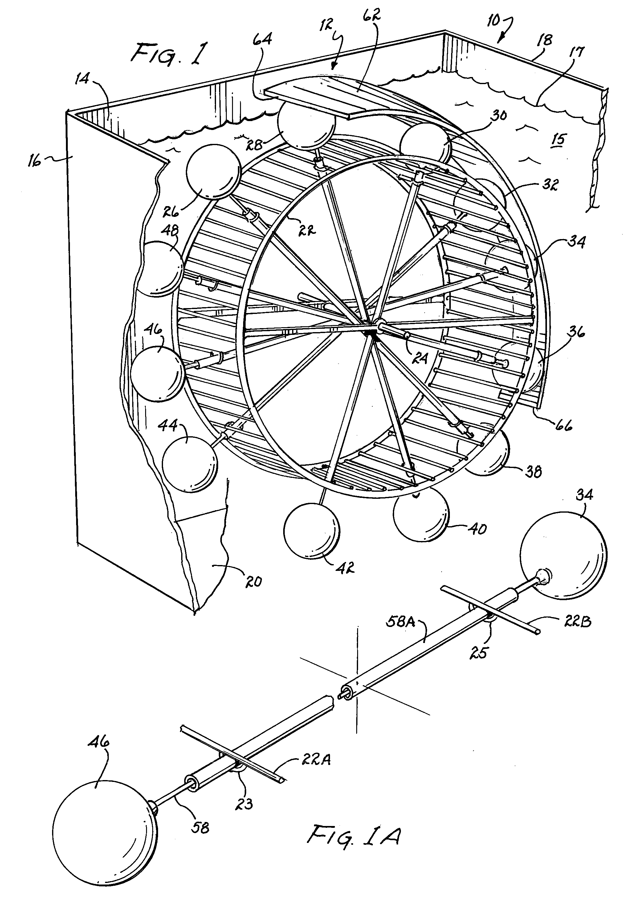
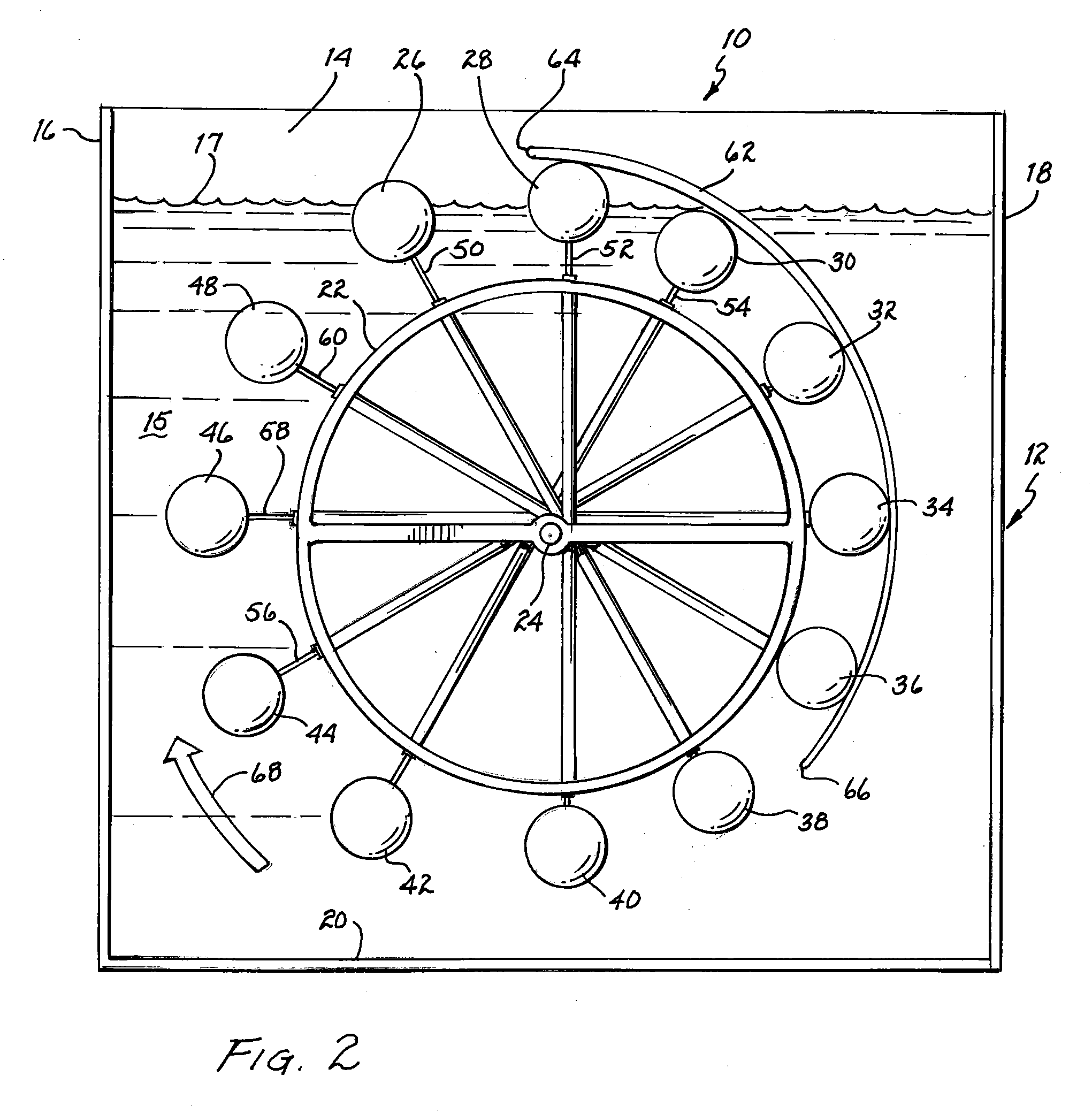
[0032]Referring to FIGS. 1 and 2, an engine 10 includes a tank or reservoir 12 for containing water or another liquid. Tank 12 includes a rear wall 14, two opposing side walls 16 and 18, a bottom wall 20, and a front wall (not shown) opposite rear wall 14. Tank 12 holds water or another liquid 15, the upper surface of which is designated by reference numeral 17. Other fluids which may be used apart from water include oils and salt water. If water is selected as the liquid 15, a layer of oil may be added, if desired, to float upon the upper surface 17 of water 15 to help lubricate moving parts. Tank 12 may be made of any suitable water-tight, non-corrosive material, including for example, glass or glazed ceramic.

[0033]A wheel 22 is mounted for rotation within tank 12. Wheel 22 includes a central shaft 24 for rotation about a central axis that extends substantially horizontal. While not shown in the drawings, the opposing ends of shaft 24 can be supported by bearing surfaces supported...


PUM


Abstract

An engine includes a liquid reservoir and a wheel mounted for rotation about a central shaft. Float members are supported symmetrically about the wheel for rotational movement and for movement toward or away from the central shaft. Each float member is coupled with a diametrically opposed float member on an opposite side of the wheel by a connecting rod. A camming surface urges passing float members toward the central shaft, and simultaneously urges a diametrically opposed float member away from the central shaft. The wheel rotates as a result of an imbalance in the buoyant forces created by the float members. Magnetic forces can supplement the camming surface for moving the float members toward and away from the central shaft.

Description

BACKGROUND OF THE INVENTION[0001]1. Field of the Invention[0002]The present invention relates generally to engines for creating motive forces, and more particularly, to an engine using bouyant elements to create rotational motion.[0003]2. Description of the Related Art[0004]As we all know, demand for energy has been continuously increasing, while the world's supply of oil, gas, coal, and other conventional fuels is fixed. Moreover, engines that operate on hydrocarbon fuels (or electrical power derived from such hydrocarbon fuels) tend to pollute the air.[0005]Others have attempted to harness the bouyant forces of flotation members within water. For example, in U.S. Pat. No. 3,907,454 to Punton, a number of air bladders are rotatably mounted between a pair of chain loops that travel over upper and lower sprockets. As each bladder reaches the lower sprocket, it is filled with compressed air through a valving system. As each bladder unit reaches its topmost position, air within the bla...

Claims


Application Information

Patent Timeline
Patent Type & Authority Applications(United States)
IPC IPC(8): F03B17/04
CPCY02E10/20F03B17/04
Inventor SILVA, THOMAS A.
Owner SILVA THOMAS A
Why Eureka
Try Eureka