Eureka AIR delivers breakthrough ideas for toughest innovation challenges, trusted by R&D personnel around the world.

Compressed Air System

Inactive Publication Date: 2010-06-17
KNORR-BREMSE SYST FUER NUTZFAHRZEUGE GMBH
View PDF6 Cites 3 Cited by
  • Summary
  • Abstract
  • Description
  • Claims
  • Application Information

AI Technical Summary

Benefits of technology

[0008]According to one preferred embodiment of the invention, at least one switchable valve is provided in a line between the compressor and the compressed air-conditioning device in order to switch off the compressed air supply when the pressure vessels for compressed-air-activated consumers are sufficiently filled. As a result, the conditioning of the compressed air can be carried out whenever the corresponding pressure vessels are to be filled. If the pressure vessels are filled, the compressed air-conditioning device with the air dryer can be switched off, with the result that the air dryer can run through a regeneration phase. This procedure is particularly efficient because the high degree of consumption of energy for drying the air has to take place only in certain phases of the operation of the compressed air system and regeneration of an air dryer cartridge is made possible.
[0009]In order to avoid a backflow in the line to the compressed air bl

Problems solved by technology

The air dryer is continuously in operation when the compressor is operating, which entails comparatively high expenditure, in particular because the air to be dried consumes, in turn, approximately 10% of the quantity of air on regenerating the desiccant.
Although an air dryer is necessary only to a limited degree for a compressed air blowing-in module for a turbo-charged internal combustion engine, if the compressed air

Method used


Image

  • Compressed Air System
  • Compressed Air System

Examples


Example

DETAILED DESCRIPTION OF THE DRAWING

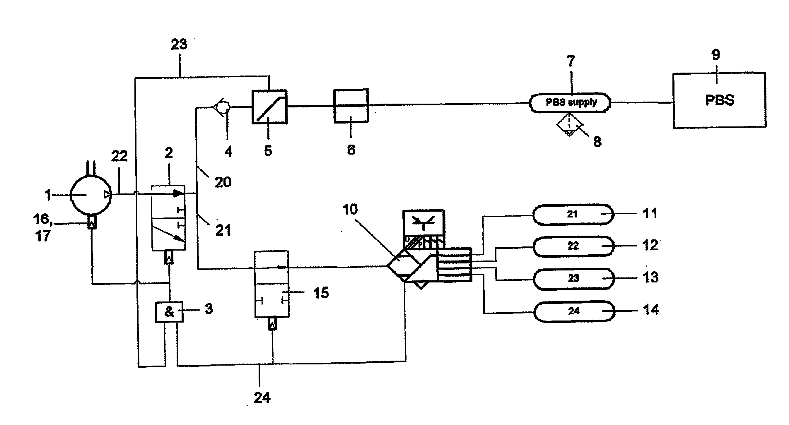
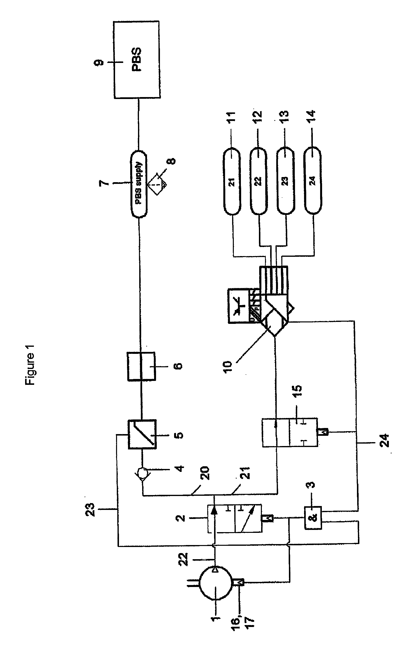
[0016]The compressed air system comprises a compressor 1 which sucks in fresh air and is driven, for example, by means of an internal combustion engine. The compressor 1 is connected via a feed line 22 to a venting valve 2 downstream of which a branching junction is provided, which divides into a first line 20 and a second line 21.

[0017]The first line 20 is used to supply a reservoir vessel 7 for supplying a compressed air blowing-in module 9, in particular for an internal combustion engine. In this context, a non-return valve 4, which is arranged upstream of a pressure-limiting valve 5, is provided downstream of the venting valve 2 in the line 20. An overflow valve 6 is provided downstream of the pressure-limiting valve 5. An automatic dewatering valve 8 is connected to the pressure vessel 7 in order to permit moisture to be carried away to a certain degree.

[0018]The second line 21 is connected via a switchable valve 15 to a compressed air-conditi...


PUM


Abstract

A compressed-air system for supplying a compress-air injection module of a turbocharged internal combustion engine and the pneumatic systems of the vehicle comprises a compressor is provided. The compressor is connected via a line to a pressure accumulator for the supply of a compressed-air injection module and to a device for compressed-air preparation having an air dryer and a pressure regulator for supplying pressure circuits for compressed-air-actuated consumers. The line for supplying the compressed-air injection module branches off upstream of the device for compressed-air preparation.

Description

CROSS-REFERENCE TO RELATED APPLICATIONS[0001]This application is a continuation of PCT International Application No. PCT / EP2008 / 006126, filed Jul. 25, 2008, which claims priority under 35 U.S.C. §119 from German Patent Application No. DE 10 2007 035 163.3, filed Jul. 25, 2007, the entire disclosures of which are herein expressly incorporated by reference.BACKGROUND AND SUMMARY OF THE INVENTION[0002]The present invention relates to a compressed air system for supplying a turbo-charged internal combustion engine. A compressor is connected to a reservoir vessel for supplying a compressed air blowing-in module, and a compressed air-conditioning device with an air dryer and a pressure regulator is provided for supplying pressure vessels for compressed-air-activated consumers.[0003]German patent document no. DE 10 2006 008 783 discloses a fresh gas supply device for a turbo-charged turbo internal combustion engine. In said engine, a compressor is operated which has an air dryer arranged d...

Claims


Application Information

Patent Timeline
IPC IPC(8): F02B33/00
CPCF02B33/44Y02T10/144F02B37/10Y02T10/12F02B9/02F02B37/04F04C25/00
Inventor GERUM, EDUARDMAYR, MATHIASNEMETH, HUBAHERGES, MICHAEL
Owner KNORR-BREMSE SYST FUER NUTZFAHRZEUGE GMBH
Why Eureka
Eureka Blog
Learn More