Brake system

a brake system and brake technology, applied in the field of brake systems, can solve the problems of increasing the failure rate of hydraulic brake systems, complicated configuration of hydraulic brakes, and the limitation of improving the reliability of braking performance and safety, so as to reduce the weight and price, and stabilize the failure ra

Active Publication Date: 2010-06-17
HYUNDAI MOBIS CO LTD
View PDF9 Cites 28 Cited by
  • Summary
  • Abstract
  • Description
  • Claims
  • Application Information

AI Technical Summary

Benefits of technology

[0008]Further, since a specific brake system added together with EWB or EMB type brake system of the present invention provides only an emergency braking force for safety, installation is not required for all of the front and rear wheels, such that it is another object of the present invention to minimize the weight and price by applying small and thin pads as compared with a main braking structure.
[0009]Embodiments of the present invention help expedite common use by satisfying legal requirements for BBW (Brake By Wire) brake systems, by further providing an emergency brake system, even if an EWB or EMB type brake system is practically applied to a vehicle.
[0015]Further, the solenoid is disposed at a side of the sub-wedge. Further, the solenoid further includes a tensile spring that applies load to the solenoid rod. According to the present invention, by practically applying an EWB or EMB type brake system to a vehicle and further providing a specific brake system that performs emergency braking for safety while achieving F-S (Fail-Safe) when a motor that is a power source fails, it is possible to also achieve stable FR (Failure Rate) in an EWB or EMB practically applied to a vehicle, as in a hydraulic brake system, and to expedite common use by satisfying legal requirements for BBW (Brake By Wire) brake system.
[0016]Further, since the BBW (Brake By Wire) brake system where the EWB or EMB type of the present invention is applied uses a specific brake system that provides only an emergency braking force, it is possible to selectively install it to the front wheel or the rear wheel, and to minimize the weight and price by applying small and thin pads as compared with a main braking structure.

Problems solved by technology

The hydraulic brakes have complicated configurations and some limits in improving reliability of braking performance and safety.
However, the electromechanical brake should be operated at 12V and achieves braking using electronic signals and electric devices, such that it has a basic limit in that FR (Failure Rate) increases as compared with the hydraulic brake system.
For example, the FR (Failure Rate) is reduced by achieving F-S (Fail-Safe) by configuring a control logic that controls the EWB or EMB and a circuit reflecting it; however, this method is not provided with a device that mechanically generates a braking force when a motor, which is a power source, fails.
Accordingly, the safety is deteriorated and the method gives a cause that makes it difficult to practically apply to vehicles due to the reduction of safety.

Method used


Image

  • Brake system
  • Brake system
  • Brake system

Examples


Embodiment Construction

[0023]Embodiments of the invention are described hereafter in detail with reference to the accompanying drawings and the embodiments are examples and can be achieved in various ways by those skilled in the art, and the present invention is not limited to the embodiments described herein.

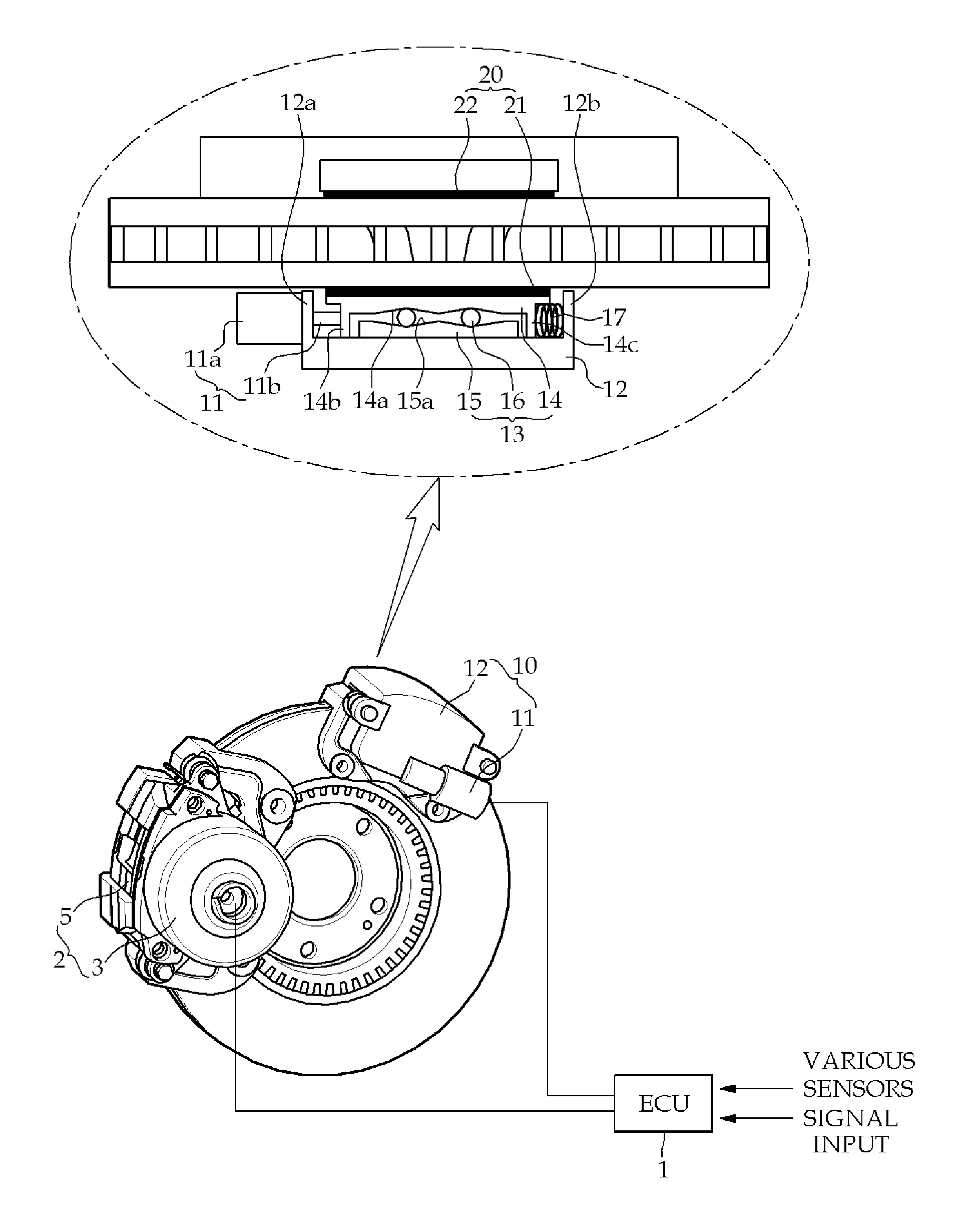
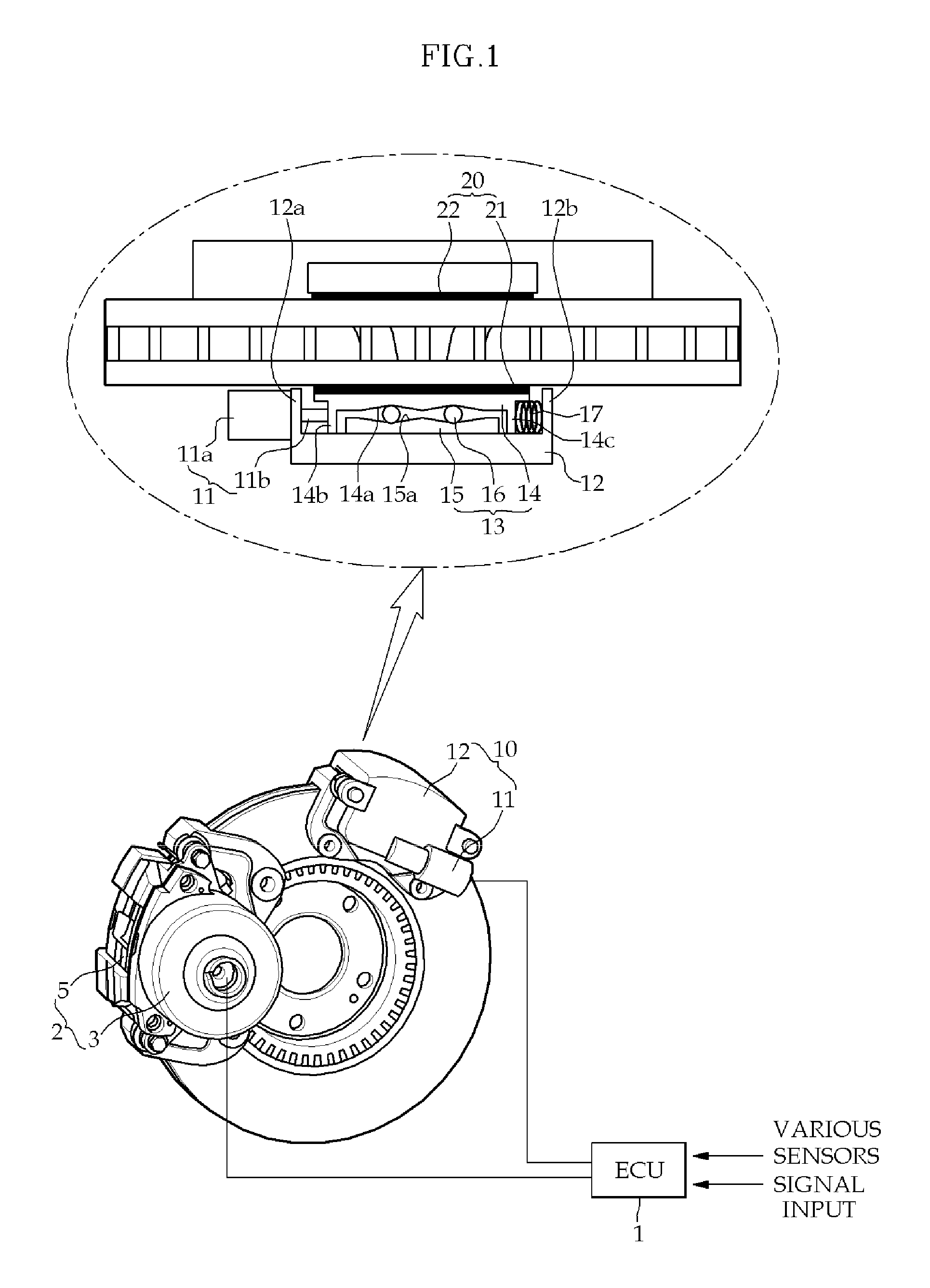
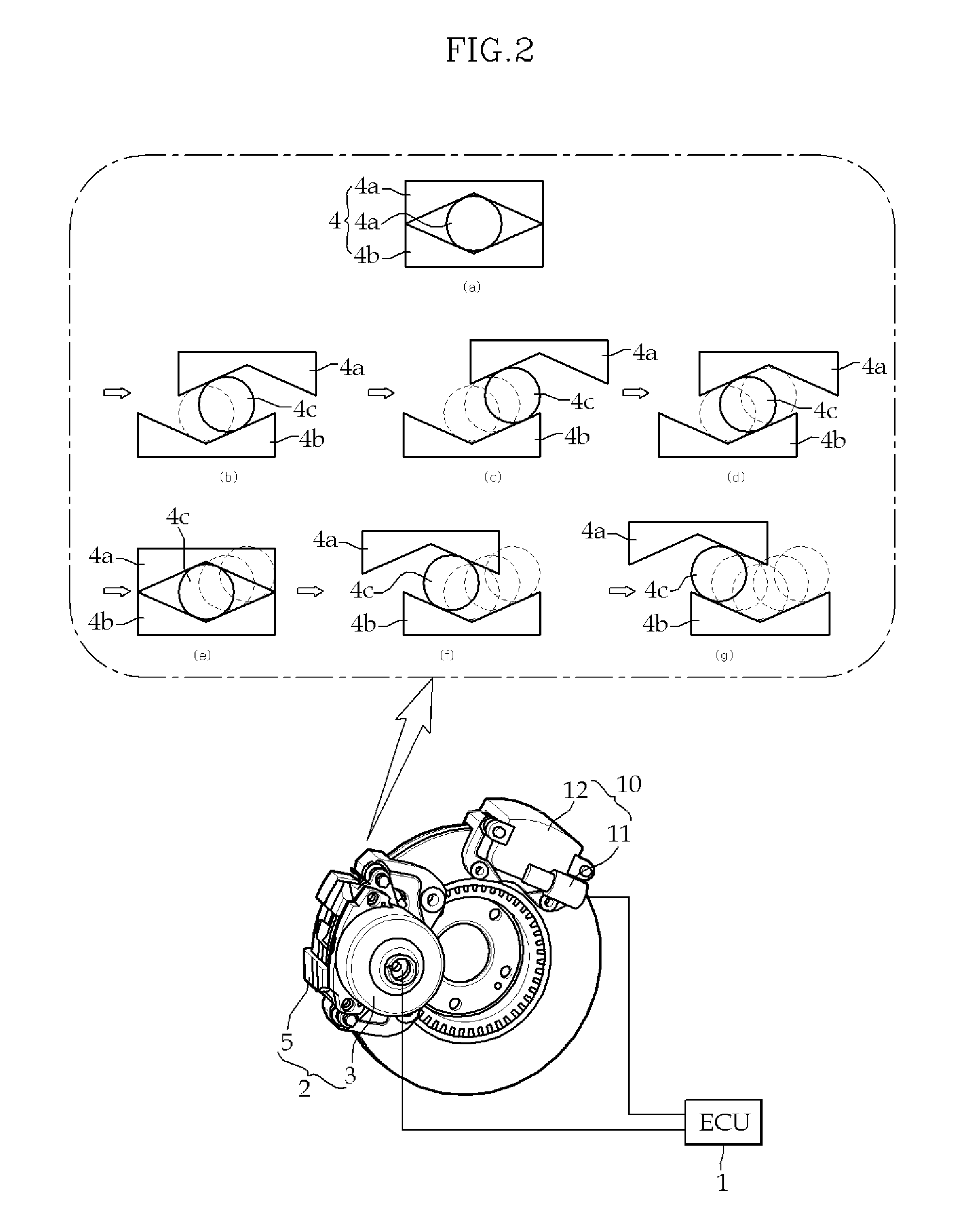
[0024]FIG. 1 is a view illustrating the configuration of a brake system having a safe braking function according to the present invention, in which the brake system of the present invention includes an ECU 1 that controls parts for braking when a brake pedal is operated, a main brake 2 that is controlled by ECU 1 by locking a wheel disc for braking in normal braking, and a sub-brake 10 that is mounted on the wheel disc and achieves sub-braking function to achieve emergency braking for safety by locking the wheel disc by control of ECU 1 that has detects failure of main brake 2.

[0025]Main brake 2 according to this embodiment, which is an EWB (Electro Wedge Brake), achieves braking by a wedge operation...


PUM


Abstract

A brake system of the present invention is a dual braking system, which includes an ECU that controls parts for braking when a brake pedal is operated, a main brake that is controlled by ECU by locking a wheel disc for braking in normal braking, and a sub-brake that is mounted on the wheel disc and achieves sub-braking function to achieve emergency braking for safety by locking the wheel disc by control of ECU that has detects failure of main brake. Therefore, it is possible to improve safety by achieving emergency braking while achieving F-S (Fail-Safe), when the motor of main brake fails. Further, it is possible to also achieve stable FR (Failure Rate) in an EWB or an EMB that is practically applied to a vehicle, as in a hydraulic brake system, and to expedite common use of brake systems where a BBW (Brake By Wire) technology, such as EMB and EWB, is applied.

Description

CROSS-REFERENCE TO RELATED APPLICATIONS[0001]The present application is based on, and claims priority from, Korean Application Serial Number 10-2008-0125713, filed on Dec. 11, 2008, the disclosure of which is hereby incorporated by reference herein in its entirety.FIELD OF THE INVENTION[0002]The present invention relates to a brake system, particularly a brake system that achieves a safe braking function using a dual brake system.BACKGROUND OF THE INVENTION[0003]In general, hydraulic brakes operate for braking by pressing pads against a disc using hydraulic pressure. The hydraulic brakes have complicated configurations and some limits in improving reliability of braking performance and safety. On the other hands, electromechanical brakes (EMB) have rather simple configurations and good reliability of braking performance. Thus, EMB have been increasingly used. The EMB achieves braking by directly converting the power of a motor into a straight moving force.[0004]As an EMB using power...

Claims


Application Information

Patent Timeline
Patent Type & Authority Applications(United States)
IPC IPC(8): F16D55/16B60T8/88
CPCB60T8/345B60T13/02B60T13/741B60T2270/83F16D65/18F16D2127/10F16D2121/22F16D2121/24F16D2123/00F16D2125/40F16D2121/20B60T17/18F16D65/14
Inventor KIM, JONGSUNG
Owner HYUNDAI MOBIS CO LTD
Why Eureka
Try Eureka