Aircraft horizontal stabilizer surface

a stabilizer and horizontal technology, applied in the direction of aircraft stabilizers, fuselages, transportation and packaging, etc., to achieve the effects of reducing weight, cost and drag, improving stabilizer performance, and reducing the size of the stabilizer

Active Publication Date: 2010-06-17
AIRBUS OPERATIONS SL
View PDF7 Cites 38 Cited by
  • Summary
  • Abstract
  • Description
  • Claims
  • Application Information

AI Technical Summary

Benefits of technology

The invention is a new design for the horizontal stabilizer of an aircraft that reduces the need for an opening in the fuselage and increases efficiency while maintaining good aerodynamic performance. The new design eliminates the need for reinforcements in the fuselage and increases rigidity in the installation zone of the horizontal stabilizer, reducing deformations under aerodynamic load. It also reduces the area of the stabilizer surface, resulting in a lighter and more efficient horizontal stabilizer.

Problems solved by technology

The technical problem addressed in this patent text is the design of aircraft with negative sweepback wings for high speed flight. These wings have advantages in terms of aerodynamic performance, but they also have structural performance complications that limit their use in commercial airplanes. These complications include increased weight and reduced efficiency of flap type high lift systems, as well as increased aerodynamic drag caused by the negative sweepback of the wing. The patent text discusses the tradeoff between the aerodynamic advantages and the structural performance of negative sweepback wings, and proposes a solution to these complications by using horizontal stabilizer surfaces with negative sweepback.

Method used


Image

  • Aircraft horizontal stabilizer surface
  • Aircraft horizontal stabilizer surface
  • Aircraft horizontal stabilizer surface

Examples


Embodiment Construction

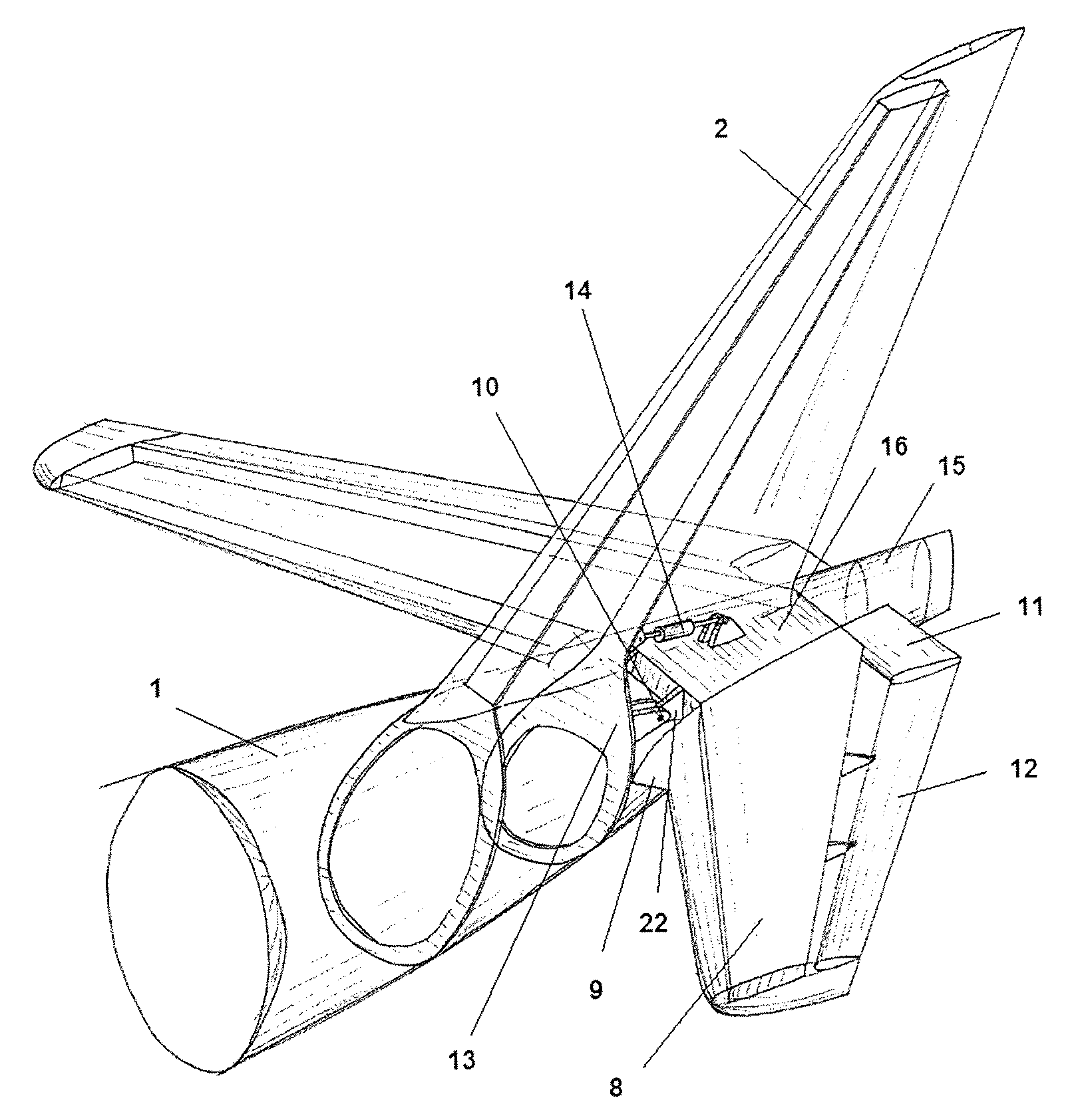
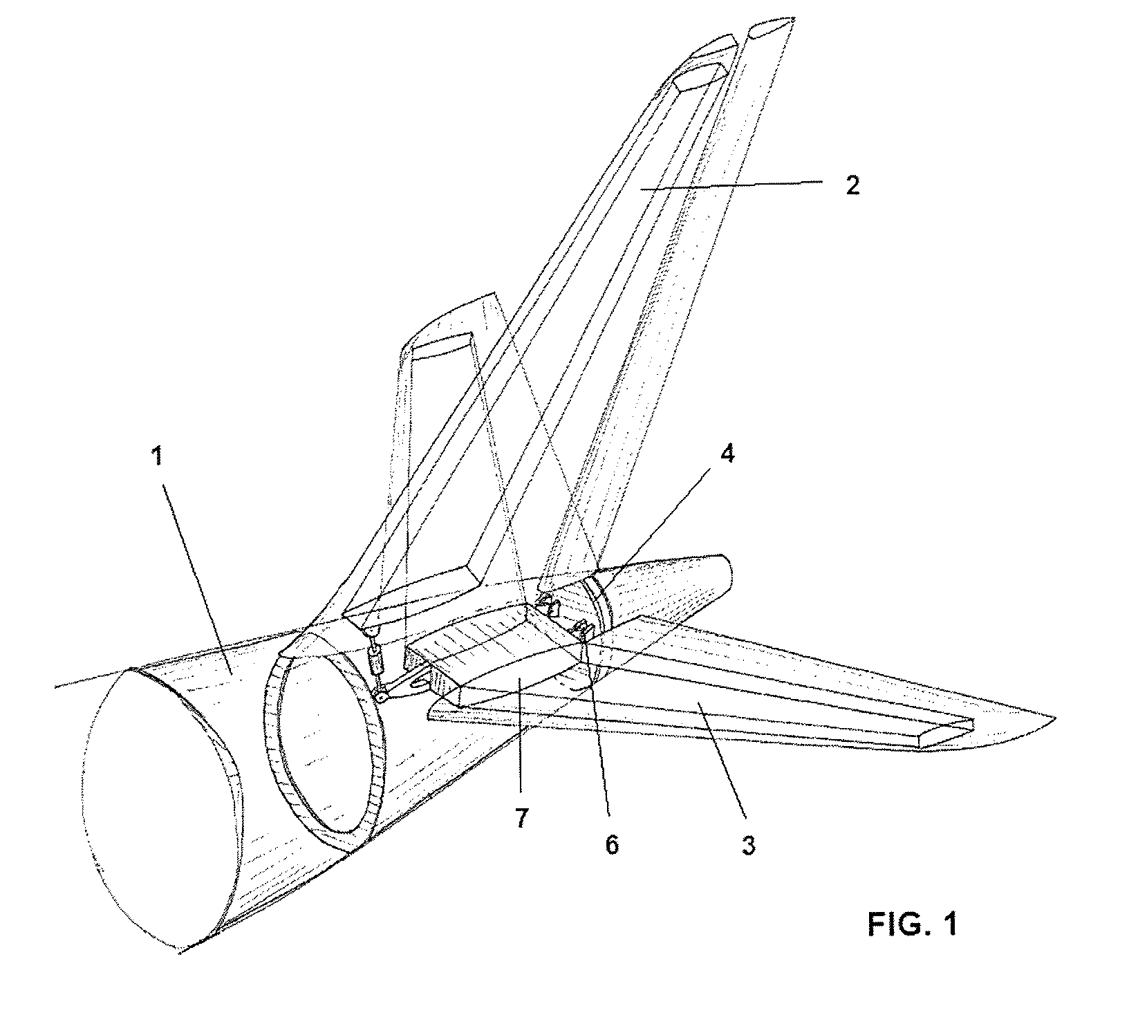
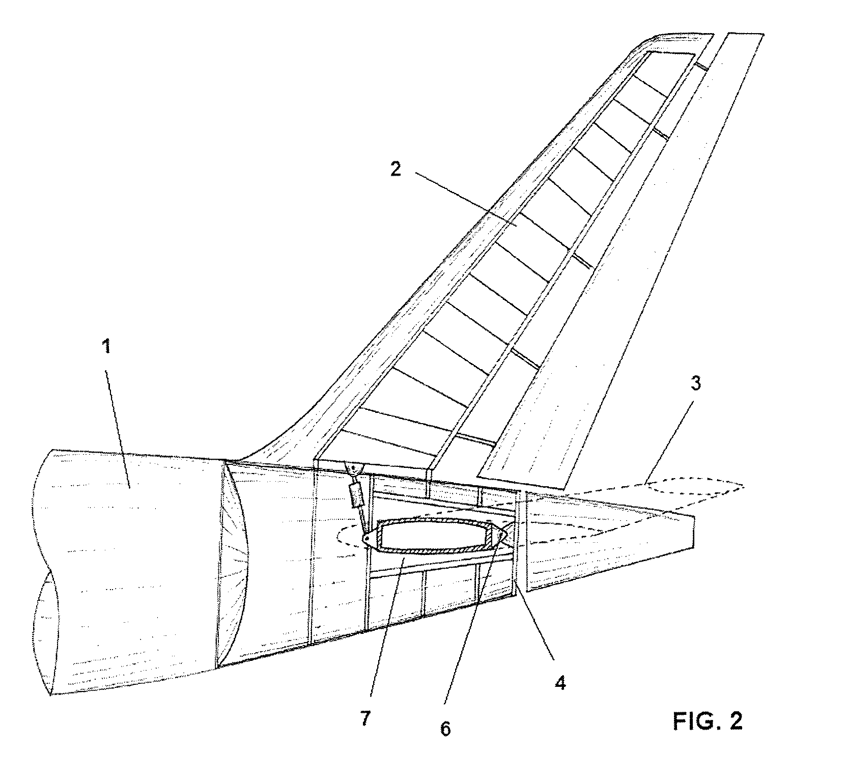
[0025]Therefore, this invention refers to a horizontal stabilizer with negative sweepback located at the rear end of an aircraft, in which the position of its aerodynamic centre is equal to the position of the aerodynamic centre of an equivalent horizontal stabilizer with conventional configuration. Moreover, the negative sweepback horizontal stabilizer of the invention avoids the need to make a structural opening in the rear end of the fuselage affected by the vertical stabilizer loads, and all this also makes it possible to take advantage of the aerodynamic advantages associated with the negative sweepback airfoils.

[0026]The characteristics of the horizontal stabilizer of this invention will be better understood with a description of a preferential embodiment of a stabilizer surface with negative sweepback of a modern commercial airplane, as shown in FIGS. 3 (lower), 4 and 5.

[0027]Thus, the invention refers to a horizontal stabilizer surface 8 with negative sweepback, such that th...


PUM


Abstract

Aircraft horizontal stabilizer surface (8) in which the sweep angle (40) of this surface (8), where this angle (40) is the one formed by the projection of the reference line of points located at 25% of the local chord (19) of the horizontal stabilizer surface (8) on a plane perpendicular to the aircraft plane of symmetry (21), and which also contains this plane to the flight direction of the aircraft with respect to the aircraft plane of symmetry (21), is less than 90 degrees, with this angle (40) being measured in the flight direction of the aircraft. In addition, the structural connection of this horizontal stabilizer surface (8) to the aircraft fuselage (1) is located at a closing frame (13) of this fuselage (1).

Description


Claims


Application Information

Patent Timeline
Owner AIRBUS OPERATIONS SL
Why Eureka
Try Eureka