Brushless Multiphase Self-Commutation (or BMSCC) And Related Invention

a multi-phase, brushless technology, applied in the direction of electronic commutators, dynamo-electric converter control, ways, etc., can solve the problems of direct application of high-frequency synthesized excitation waveform to low-frequency, inability to solve control asymptotically, and inability to estima

Active Publication Date: 2010-06-17
KLATT FREDERICK WILLIAM
View PDF8 Cites 16 Cited by
  • Summary
  • Abstract
  • Description
  • Claims
  • Application Information

AI Technical Summary

Benefits of technology

[0081]Still another object of the present invention is to provide a mechanical adjustment means between the primary and secondary bodies of the PDF-HFT for simultaneously enhancing the electronic adjustment and re-fabrication control means.
[0082]Still another object of the present invention is to provide environmental stress immunity to sensitive electrical and electronic components because the BMSCC is the only electronic control means for electric apparatus that requires placement of sensitive components near the movement of the moving body of the electric apparatus and into the same hostile environment experienced by the electric machine.

Problems solved by technology

Invented in the early 1970's, FOC could only become what is considered today's most state-of-art electronic excitation control because enormous advances in electronic processing performance and density satisfied the formidable processing complexity of FOC in some situations.
Trait 1, the resolution of control is asymptotically limited, is closely determined by the power and speed of the electronic computers, and is inherently unstable; particularly, at low excitation frequencies, where measurement and estimation become elusive.
Further, the high frequency synthesized excitation waveform is directly applied to the low frequency designed active winding set or the multiphase AC power source with detrimental consequences, if not properly compensated for.
Further, the inventor did not understand the extraordinary environmental stress placed on the electrical and electronic equipment of the issued U.S. patents.
For instance, the electrical and electronic components are directly exposed to the harsh environment of the electric machine installation because the issue patents disclose the only electric machine that must closely couple all electrical and electronic components to the moving shaft of the electric machine.
Consequently, the issued U.S. patents did not understand or disclose the modulation requirements for Power Factor control and speed-torque control or the environmental requirements for the sensitive electrical and electronic equipment for practical operation of the Electric Rotating Apparatus and Electric Machine.
Without synchronization between the rotating (or moving) magnetic fields on each side of the air gap, torque (or force) pulsation would result and no useful average power could be produced.
Synchronous electric machines are inherently unstable, do not exhibit startup torque, and cannot operate standalone, because the mutually exclusive maintenance of the two rotating magnetic fields is prone to loss of synchronism with potentially devastating results.Note: Any Electric Machine that independently maintains the synchronized rotating magnetic fields on each side of the air gap without the need to maintain slip for speed based induction even while potentially experiencing slip is considered a Synchronous Electric Machine.
In all other electric machines, the real estate of the rotor core assembly (or in some cases the stator core assembly) is considered underutilized because the rotor is only a passive participant in the energy conversion process and does not add real power to the system.
However, the Wound-Rotor Doubly-Fed Electric Machine incorporates sliding contacts (i.e., multiphase slip ring assembly) for an independent electrical excitation connection to the rotating active winding set and is acutely unstable at synchronous speed, where the frequency and voltage of the rotor excitation is difficult to measure or synthesize by any derivative of FOC electronic control.
Since permanent magnets do occupy core real estate but do not participate in the energy conversion process, the core real estate of the permanent synchronous electric machine is not optimally utilized as is the core real estate of the wound-rotor doubly-fed electric machine.
The steel magnetic core has its own deficiencies, such as Eddy Current loss and a finite Flux Density saturation limit.
However, high speed singly-fed electric machines require high excitation frequency, which leads to high core loss and higher material cost to mitigate the higher core loss.
High frequency modulation exposes the windings and power source of the electric machine to high frequency harmonics, which are detrimental to bearing and winding insulation life.
High frequency harmonics also cause high core and electrical loss.

Method used


Image

  • Brushless Multiphase Self-Commutation (or BMSCC) And Related Invention
  • Brushless Multiphase Self-Commutation (or BMSCC) And Related Invention
  • Brushless Multiphase Self-Commutation (or BMSCC) And Related Invention

Examples


Embodiment Construction

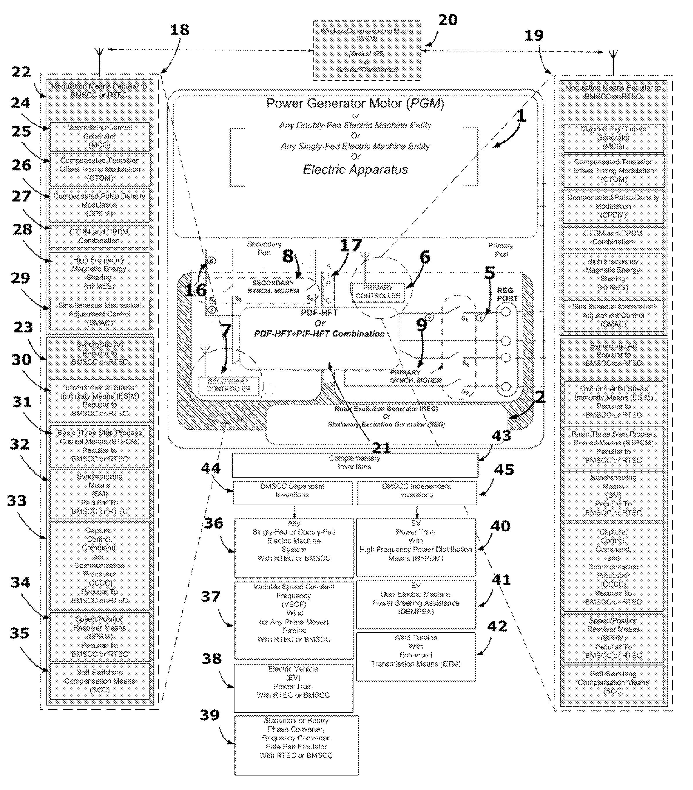
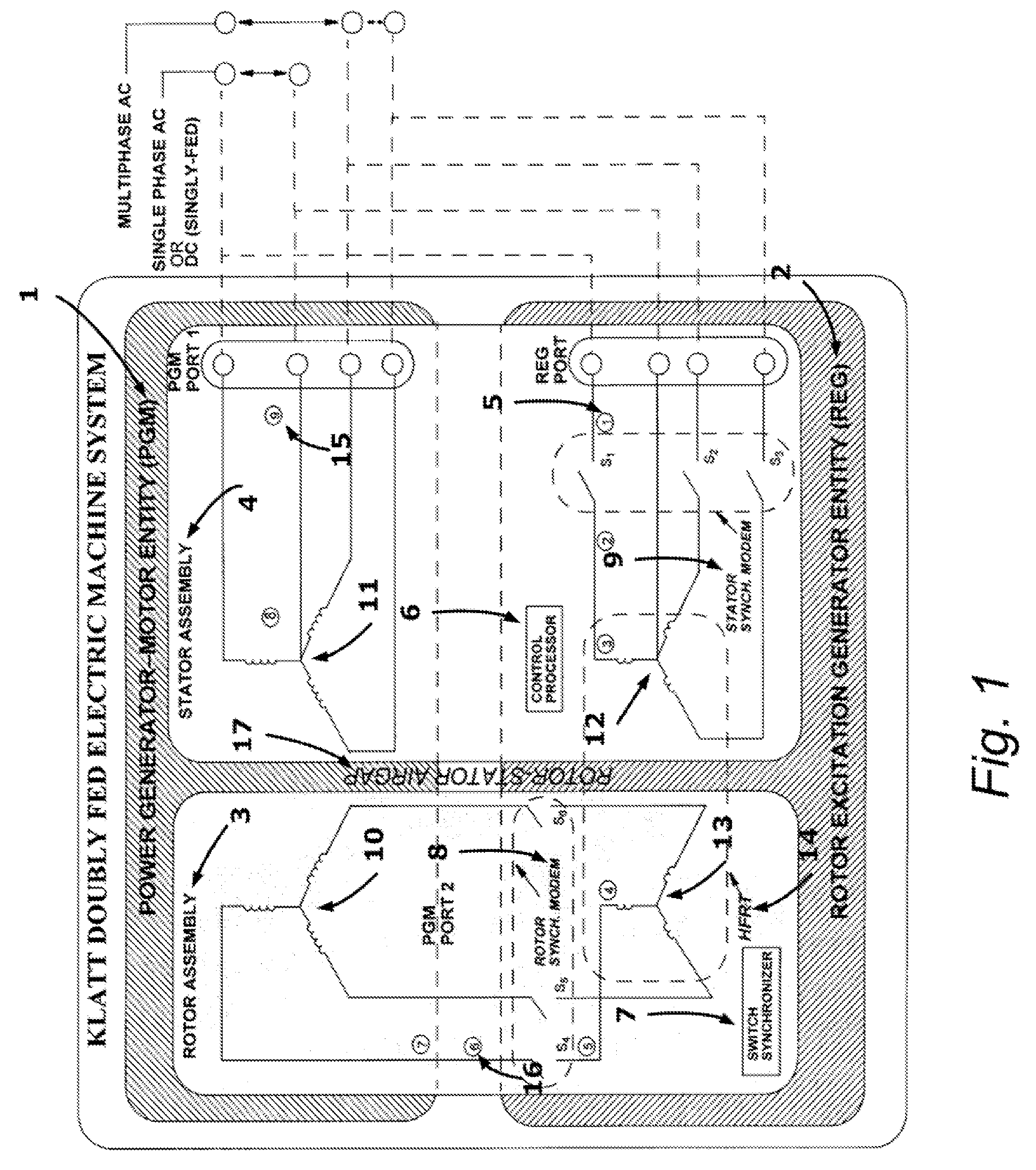
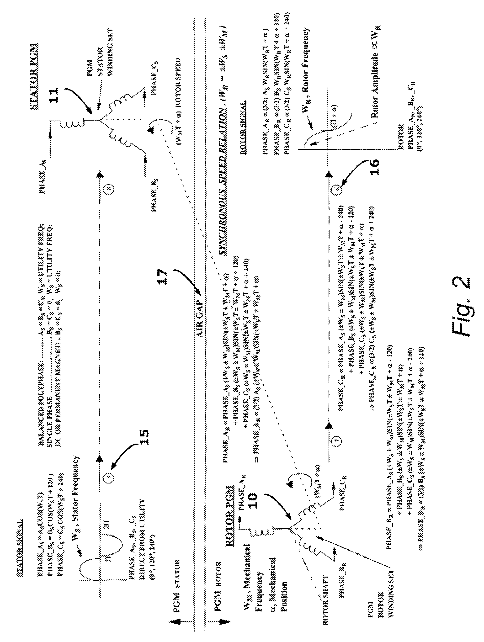
[0117]True Brushless Multiphase Self-Commutation Control (BMSCC) or Real Time Emulation Control (RTEC) is a contact-less means of propagating conditioned or re-fabricated electrical power between relatively isolated bodies while naturally inducing any potential mechanical speed or positional movement between the bodies onto the original electrical waveform by means of an Electro-magnetic Self-Commutator (i.e., electromagnetic computer or rotor excitation generator). True Brushless Multiphase Self-Commutation Control (BMSCC) is a new embodiment of a Rotor Excitation Generator (REG). A Rotor Excitation Generator is any device that provides Rotor Excitation Generation, which is synonymous with electromagnetic self-commutation. Previously, the only example of a REG was a component associated with the Electric Rotating Apparatus and Electric Machine patents of this inventor (U.S. Pat. No. 4,459,530, U.S. Pat. No. 4,634,950, U.S. Pat. No. 5,237,255, and U.S. Pat. No. 5,243,268). BMSCC pro...


PUM


Abstract

Brushless Multiphase Self-Commutation Control (or BMSCC), also known as Real Time Emulation Control (or RTLC), is a contact-less means for powering any electric apparatus with “conditioned” or “re-fabricated” multiphase electrical excitation that is synchronized to the movement of the electric apparatus. BMSCC inherently phase-locks the frequency of excitation to any speed or position of the electric apparatus being controlled by a natural electromagnetic processing means and as a result, the BMSCC is an Electromagnetic Self-Commutator. BMSCC should never be confused with any derivative of Field Oriented Control, which is the other means of conditioning speed-synchronized electrical excitation by iteratively performing “speed-variant-to-speed-invariant” transformations and frequency synthesis by the unnatural processing means of an electronic computer. The control flexibility of BMSCC realizes additional synergistic or complementary electric apparatus inventions as shown in the illustration.

Description

PRIOR ART[0001]U.S. Pat. Nos. 4,459,540; 4,634,950; 5,237,255 and 5,243,268 of this inventor disclosed the “Electric Rotating Apparatus and Electric Machine” system that incorporates an inherent phase-locking means for supplying speed-synchronized, multiphase electrical power to the moving active winding sets of an electric machine entity, which is an electric motor or electric generator, without electrical-mechanical contacts (i.e., brush-less). As disclosed by the aforementioned patents of this inventor, the means for providing speed-synchronized power to the Power Generator Motor (or PGM), which is a Wound-Rotor Doubly-Fed Electric Machine entity or a stator based permanent magnet singly-fed electric machine entity, is a Rotor Excitation Generator (or REG). The REG-PGM combination has not been commercially available because many years of continued research, development, and prototyping by this inventor have shown new inventions that are crucial for practical control and operation...

Claims


Application Information

Patent Timeline
Patent Type & Authority Applications(United States)
IPC IPC(8): H02P25/08H02K37/02H02K9/00
CPCH02P6/001B60Q1/30F21V33/0076Y02E10/725F21Y2101/02E01F9/06E01F9/553H02P6/34F21Y2115/10Y02E10/72
Inventor KLATT, FREDERICK WILLIAM
Owner KLATT FREDERICK WILLIAM
Why Eureka
Try Eureka