Egg examining device

a technology of egg trays and examining devices, which is applied in the field of egg examining devices, can solve the problems of low resistance to egg trays waste, measurement variations and errors, and large mechanical systems of this type, and achieves the effect of simple and cost-effective solutions

Active Publication Date: 2013-03-19
CEVA SANTE ANIMALE
View PDF8 Cites 4 Cited by
  • Summary
  • Abstract
  • Description
  • Claims
  • Application Information

AI Technical Summary

Benefits of technology

[0008]The use of a coherent laser source according to the invention makes it possible to obtain a coherent optical beam which is fine and more concentrated and which penetrates the egg shell better than the light beam of a simple light emitting diode which means the light source does not necessarily have to be arranged on the side facing or exactly opposite the receiving means. The use of a coherent laser source therefore allows the light source and the receiving means to be arranged in many positions. According to the invention, it is therefore possible to arrange the light source in such a way that it is protected from waste which falls from the egg trays. The device according to the invention does not have to be serviced as often, is more stable and produces results which are more accurate.
[0009]According to one embodiment, said laser source is arranged below the eggs to be examined, the optical beam forming a non-null angle with respect to the vertical, for example between 5 and 45°, for example approximately 15°. Advantageously, said laser source is arranged below a protective plate. Since its beam is fine and coherent, the laser source may be arranged further away from the egg than the light sources of the prior art, without illuminating the adjacent eggs on the tray and with a non-null beam angle with respect to the vertical, in such a way that the laser source may be protected from waste, in particular below a protective plate.
[0016]According to another feature, the examining device further comprises synchronisation means, such as an additional receiver for receiving ambient light waves and a timing device for synchronising the transparency measurements taken by the receiving means and the pulses of the laser source on the energy frequency of the ambient light waves, in the vicinity of the peak S of the time periods T of the energy of the ambient light waves. According to the invention, said synchronisation is a simple and cost-effective solution from a mechanical, electronic and optical point of view for providing immunity against the ambient light waves. Each transparency measurement comprises obtaining, in the vicinity of a peak S, a first value val1 corresponding to the level of light energy on the receiving means without the laser source associated therewith being activated, then obtaining a second value val2 corresponding to the level of light energy on the receiver with the laser source associated therewith activated, the transparency measurement being obtained by simply subtracting the first value val1 from the second value val2.

Problems solved by technology

The main drawback of said vertical examination systems is their low resistance to waste originating from the egg trays.
The waste, such as bits of shell or the contents of broken eggs, feathers or other organic material, fall by means of gravity onto the emitters or receivers arranged below the trays which results in measurement variations and errors.
Mechanical systems of this type are bulky and of complex design.

Method used


Image

  • Egg examining device
  • Egg examining device
  • Egg examining device

Examples


Embodiment Construction

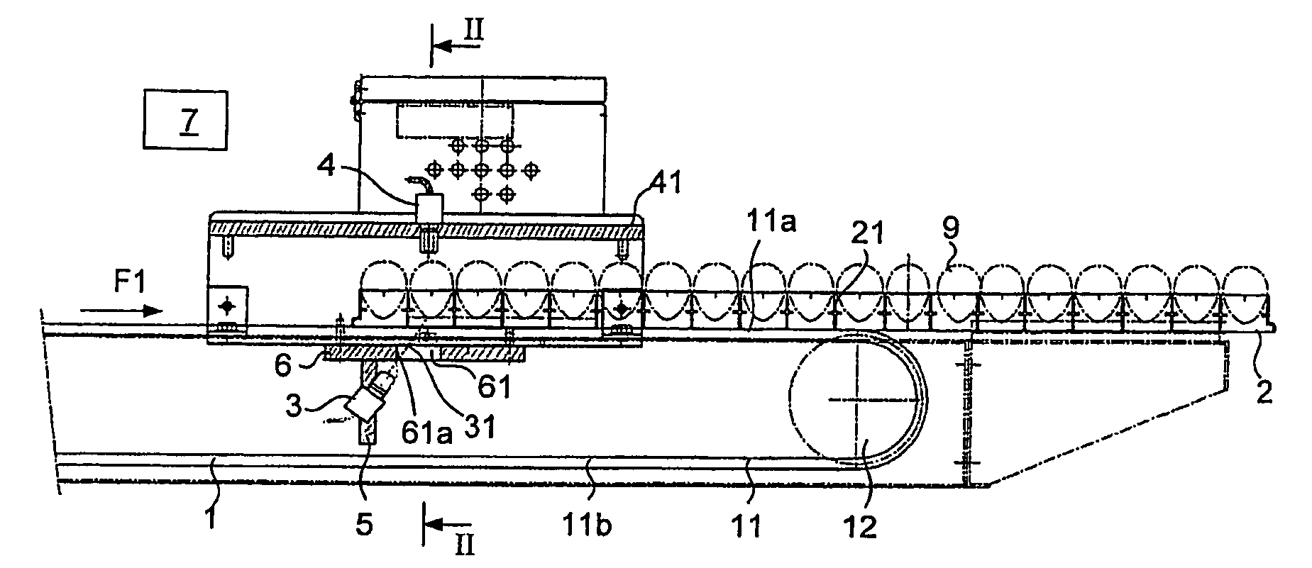
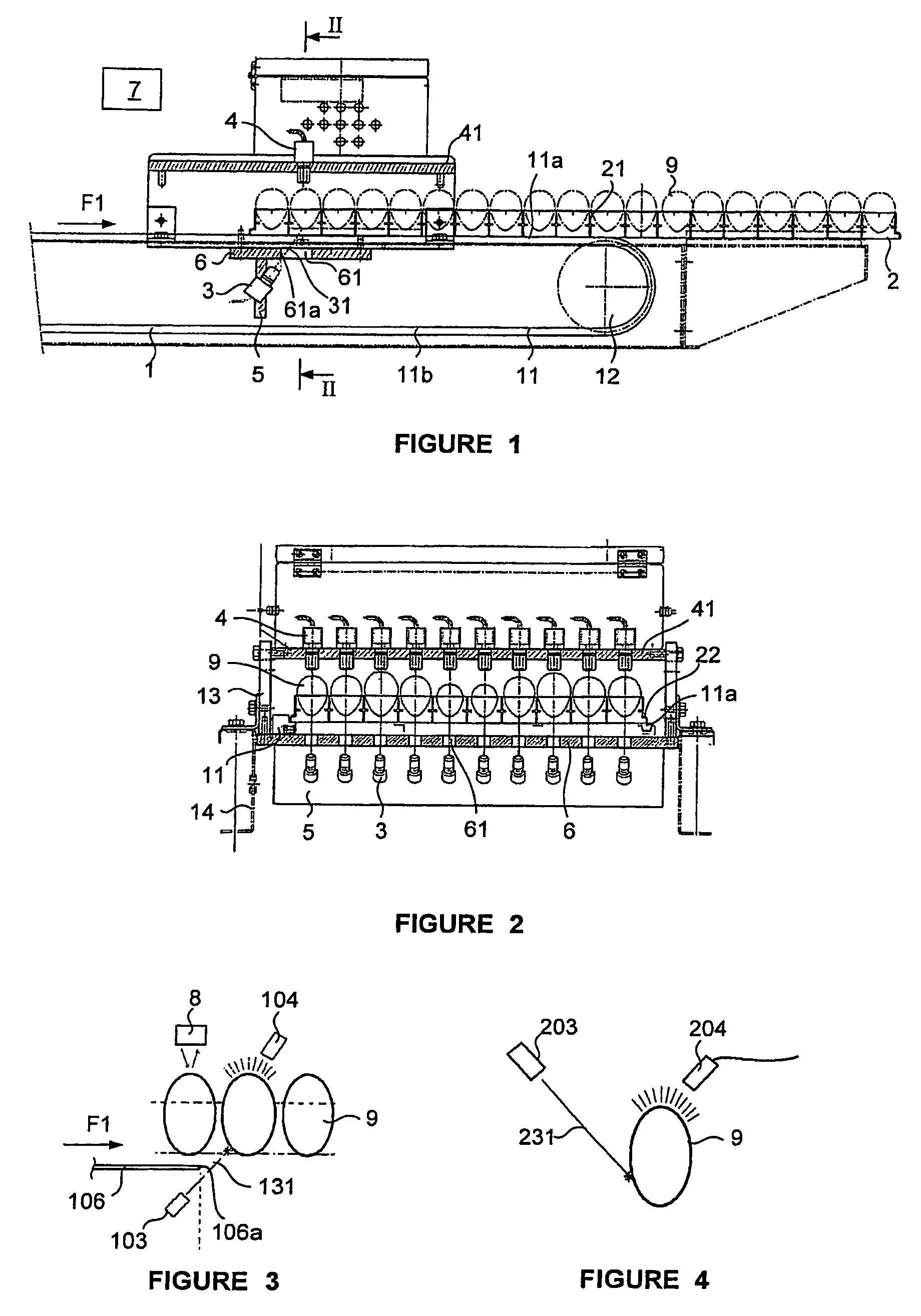
[0025]With reference to FIGS. 1 and 2, the device according to the invention comprises conveying means 1 for transporting incubation trays 2 of eggs along a conveying path, along which emission means or emitters 3 and receiving means or receivers 4 are arranged.

[0026]The conveying means 1 comprise an endless belt-type conveyor which transports the trays in the direction of movement F1. The conveyor is formed of two belts and two parallel chains 11 for synchronised transportation, each mounted in a looped manner on a preceding intermediate gear wheel and a following intermediate gear wheel 12. The spacing between the two chains is determined in such a way that the side edges 22 of the plates 2 abut the upper sides 11a of the two chains.

[0027]In the example shown, the device is configured for treating eggs 9 arranged on known “rectangular” trays 2 comprising parallel transverse rows of recesses or wells 21 which are open at the bottom, such as the incubation trays sold under the trade...


PUM

PropertyMeasurementUnit
surface areaaaaaaaaaaa
surface areasaaaaaaaaaa
angleaaaaaaaaaa

Abstract

The present invention relates to an automatic egg examining device for differentiating between fertilized eggs and unfertilized eggs, comprising emission means (3), which comprise, for each egg to be examined, at least one coherent laser source forming a coherent optical beam (31) directed at an egg (9) to be examined, reception means (4), which receive the light flux passing through the egg, and data processing means (7), which process the light flux received by said reception means in order to determine the state—fertilized or unfertilized—of the egg.

Description

CROSS REFERENCE TO RELATED-APPLICATIONS[0001]This is a national stage of PCT / FR2006 / 002815 filed Dec. 20, 2006.FIELD OF THE INVENTION[0002]The present invention relates to an egg examining device for differentiating between fertilized and unfertilized eggs.BACKGROUND OF THE INVENTION[0003]In the poultry industry, in particular the chicken industry, automatic egg examining devices using the transparency of the egg in order to differentiate between fertilized and unfertilized eggs are known. These devices comprise emission means for emitting a light beam in the direction of an egg to be examined, receiving means for receiving the light beam passing through the egg, and means for processing data regarding the light beam received by said receiving means so as to determine the state of the egg. As a function of the level of absorption of the light beam passing through the egg, or the level of transparency of the egg, the data processing means can differentiate between fertilized eggs, i....

Claims


Application Information

Patent Timeline
Patent Type & Authority Patents(United States)
IPC IPC(8): G01N33/08A01K43/00
CPCA01K43/00G01N33/085
Inventor NADREAU, MICHAELCROGUENNEC, ROBERT
Owner CEVA SANTE ANIMALE
Why Eureka
Try Eureka