Thermal cleaning of individual jetting module nozzles

a technology of jetting module and nozzle, which is applied in the direction of printing, inking apparatus, other printing apparatus, etc., can solve the problems of reducing print quality, and achieve the effect of higher activation component and higher activation componen

Inactive Publication Date: 2010-06-17
EASTMAN KODAK CO
View PDF31 Cites 9 Cited by
  • Summary
  • Abstract
  • Description
  • Claims
  • Application Information

AI Technical Summary

Benefits of technology

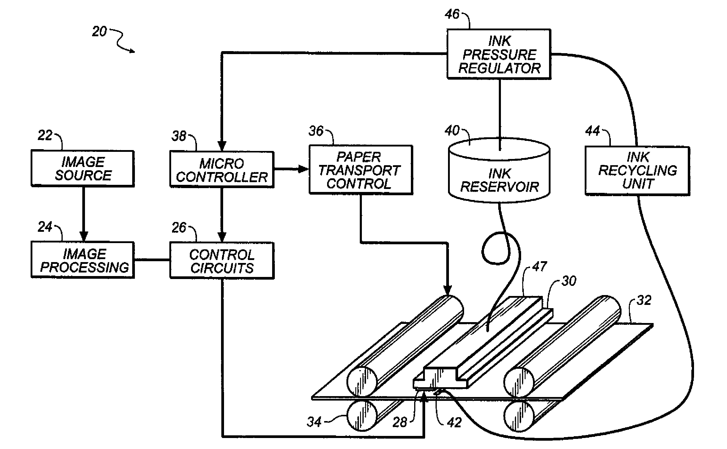
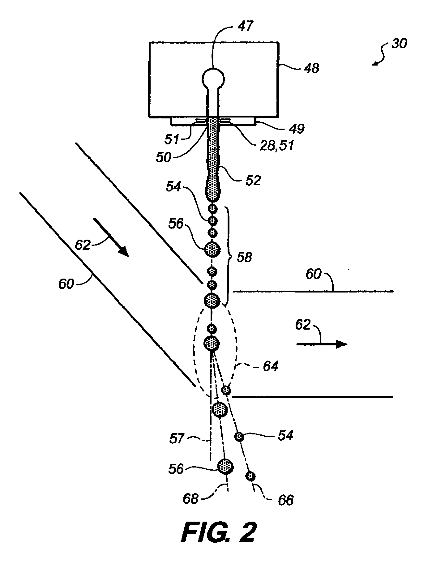
[0004]According to one aspect of the present invention, a liquid ejection device includes a jetting module including an array of nozzles, a thermal stimulation device associated with each nozzle of the array of nozzles, and a controller in electrical communication with each thermal stimulation device. The controller is configured to provide a first activation waveform to each thermal stimulation device and to provide a second activation waveform to each thermal stimulation device to clean the associated nozzle with liquid emitted from the associated nozzle. The second activation waveform has a higher activation component when compared to the first activation waveform.
[0005]According to another aspect of the invention, a method of cleaning a liquid ejection device includes providing a jetting module including an array of nozzles; providing a thermal stimulation device associated with each nozzle of the array of nozzles; using a controller in electrical communication with each thermal stimulation device to provide a first activation waveform to each thermal stimulation device; and using the controller to provide a second activation waveform to each thermal stimulation device to clean the associated nozzle with liquid emitted from the associated nozzle, the second activation waveform having a higher activation component when compared to the first activation waveform.

Problems solved by technology

Debris, for example, dust or dirt, when present in or around nozzles of a printhead can cause ink drops ejected from the nozzle to be misdirected or have inconsistencies in drop size or drop shape which may result in reduced print quality.

Method used


Image

  • Thermal cleaning of individual jetting module nozzles
  • Thermal cleaning of individual jetting module nozzles
  • Thermal cleaning of individual jetting module nozzles

Examples


Embodiment Construction

[0019]The present description will be directed in particular to elements forming part of, or cooperating more directly with, apparatus in accordance with the present invention. It is to be understood that elements not specifically shown or described may take various forms well known to those skilled in the art. In the following description and drawings, identical reference numerals have been used, where possible, to designate identical elements.

[0020]The example embodiments of the present invention are illustrated schematically and not to scale for the sake of clarity. One of the ordinary skills in the art will be able to readily determine the specific size and interconnections of the elements of the example embodiments of the present invention.

[0021]As described herein, the example embodiments of the present invention provide a printhead and / or printhead components typically used in inkjet printing systems. However, many other applications are emerging which use inkjet printheads t...


PUM


Abstract

A liquid ejection device includes a jetting module including an array of nozzles; a thermal stimulation device associated with each nozzle of the array of nozzles; and a controller in electrical communication with each thermal stimulation device. The controller is configured to provide a first activation waveform to each thermal stimulation device and to provide a second activation waveform to each thermal stimulation device to clean the associated nozzle with liquid emitted from the associated nozzle. The second activation waveform has a higher activation component when compared to the first activation waveform.

Description

CROSS REFERENCE TO RELATED APPLICATIONS[0001]Reference is made to commonly-assigned, U.S. patent application Ser. No. ______ (Docket 95196), entitled “PRESSURE MODULATION CLEANING OF JETTING MODULE NOZZLES”, filed concurrently herewith.FIELD OF THE INVENTION[0002]This invention relates generally to the field of digitally controlled printing devices, and in particular to techniques for cleaning individual nozzles of a jetting module.BACKGROUND OF THE INVENTION[0003]Debris, for example, dust or dirt, when present in or around nozzles of a printhead can cause ink drops ejected from the nozzle to be misdirected or have inconsistencies in drop size or drop shape which may result in reduced print quality. Various techniques for removing debris located in or around the nozzles of a printhead are known and include, for example, utilizing a cleaning fluid and / or a mechanical cleaning assembly to clean the nozzles of the printhead.SUMMARY OF THE INVENTION[0004]According to one aspect of the p...

Claims


Application Information

Patent Timeline
Patent Type & Authority Applications(United States)
IPC IPC(8): B41J29/38B41J2/165
CPCB41J2/03B41J2/105B41J2/16526B41J2202/16B41J2002/022B41J2002/031B41J2002/033B41J2/185
Inventor GARBACZ, GREGORY J.LOPEZ, ALI G.HSU, CHANG-FANG
Owner EASTMAN KODAK CO
Why Eureka
Try Eureka