
Digital image capture device and brightness correction method thereof

Inactive Publication Date: 2010-06-17
ALTEK CORP
View PDF5 Cites 14 Cited by
  • Summary
  • Abstract
  • Description
  • Claims
  • Application Information

AI Technical Summary

Benefits of technology

[0013]As described above, the present invention provides a method for correcting the brightness of a digital image and a digital image capture device thereof based on different light measuring areas in the digital image. According to the distances from the light measuring areas to the shot object, the digital image capture device respectively sets a dedicated brightness correction value for each light measuring area and records the brightness correction values to a shading table. Directing to shot objects with different distances / shooting magnifications, the shading table with the corresponding distance is loaded to prevent over-exposure of some areas of the digital image when a single gain value is employed to compensate the whole digital image.

Problems solved by technology

Due to physical properties, the lens set in the digital image capture device may cause the problem of non-uniform brightness distribution during the imaging of the shot object under the light source.
Meanwhile, if the strobe is used for compensating the brightness, the non-uniform brightness distribution becomes even more apparent.
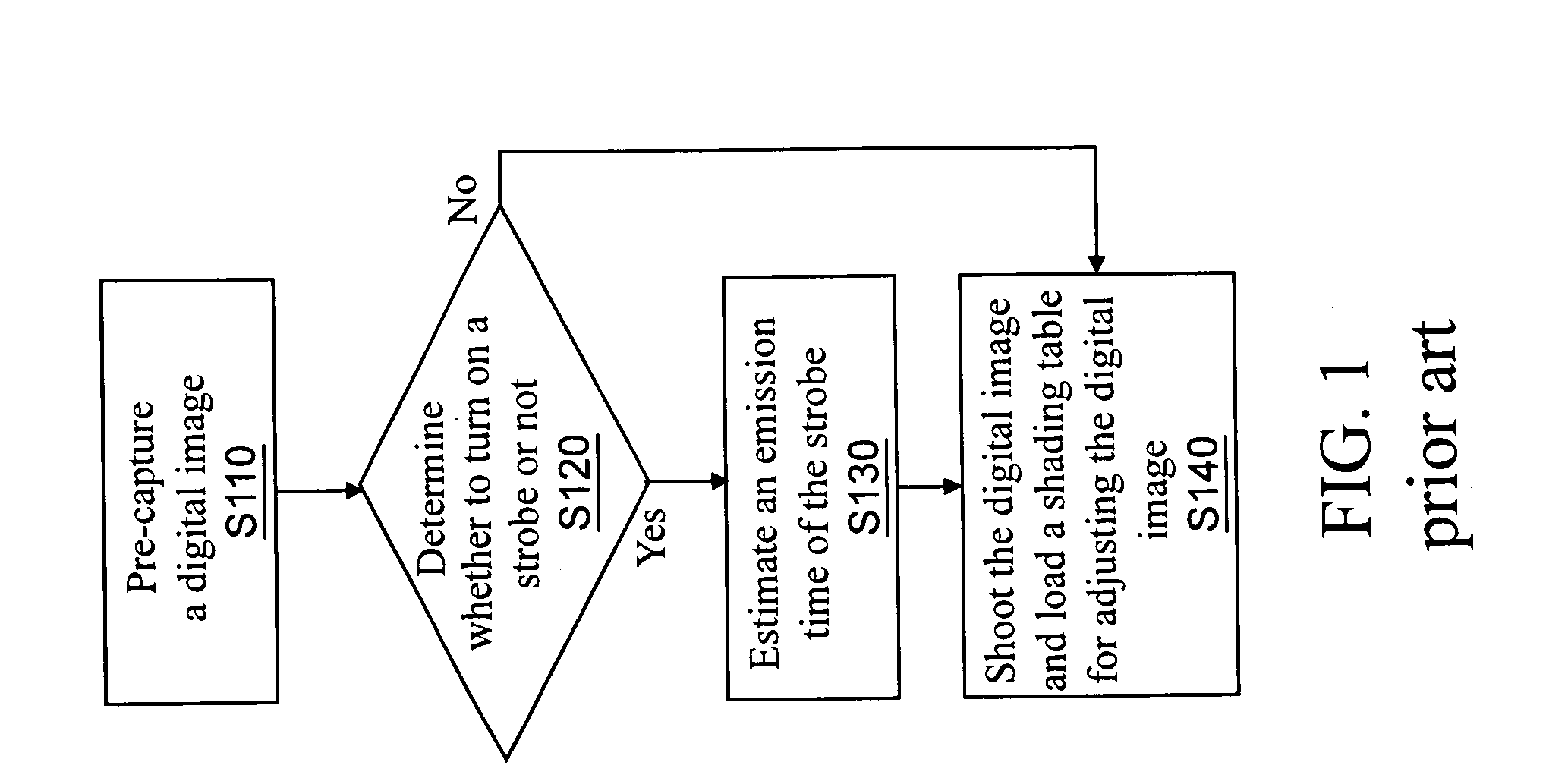
If only a shading table is applied to all the shooting environments, the problem that the long-shot gain is too much while the close-shot gain is insufficient may occur to the digital image at different focusing object distances, and vice versa.
In this manner, the modified digital image appears unnatural.

Method used


Image

  • Digital image capture device and brightness correction method thereof
  • Digital image capture device and brightness correction method thereof
  • Digital image capture device and brightness correction method thereof

Examples


Embodiment Construction

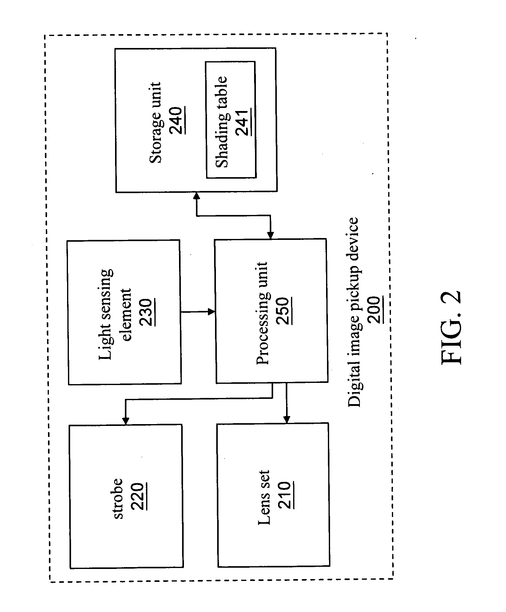
[0023]FIG. 2 is a schematic architectural view of the present invention. The digital image capture device 200 of the present invention includes a lens set 210, a strobe 220, a light sensing element 230, a storage unit 240, and a processing unit 250. The lens set 210 is used to adjust a focal length and a zoom ratio of a shot object. The light sensing element 230 is electrically connected to the lens set 210, for receiving an image signal of the shot object through the lens set 210. The storage unit 240 is electrically connected to the light sensing element 230, for storing the digital image received by the light sensing element 230 and a shading table 241. The processing unit 250 is electrically connected to the strobe 220, the light sensing element 230, and the storage unit 240, for adjusting an output value of the strobe 220 according to the shading table 241 established through pre-shooting.

[0024]In order to explicitly describe the operation of the present invention, a schematic ...


PUM


Abstract

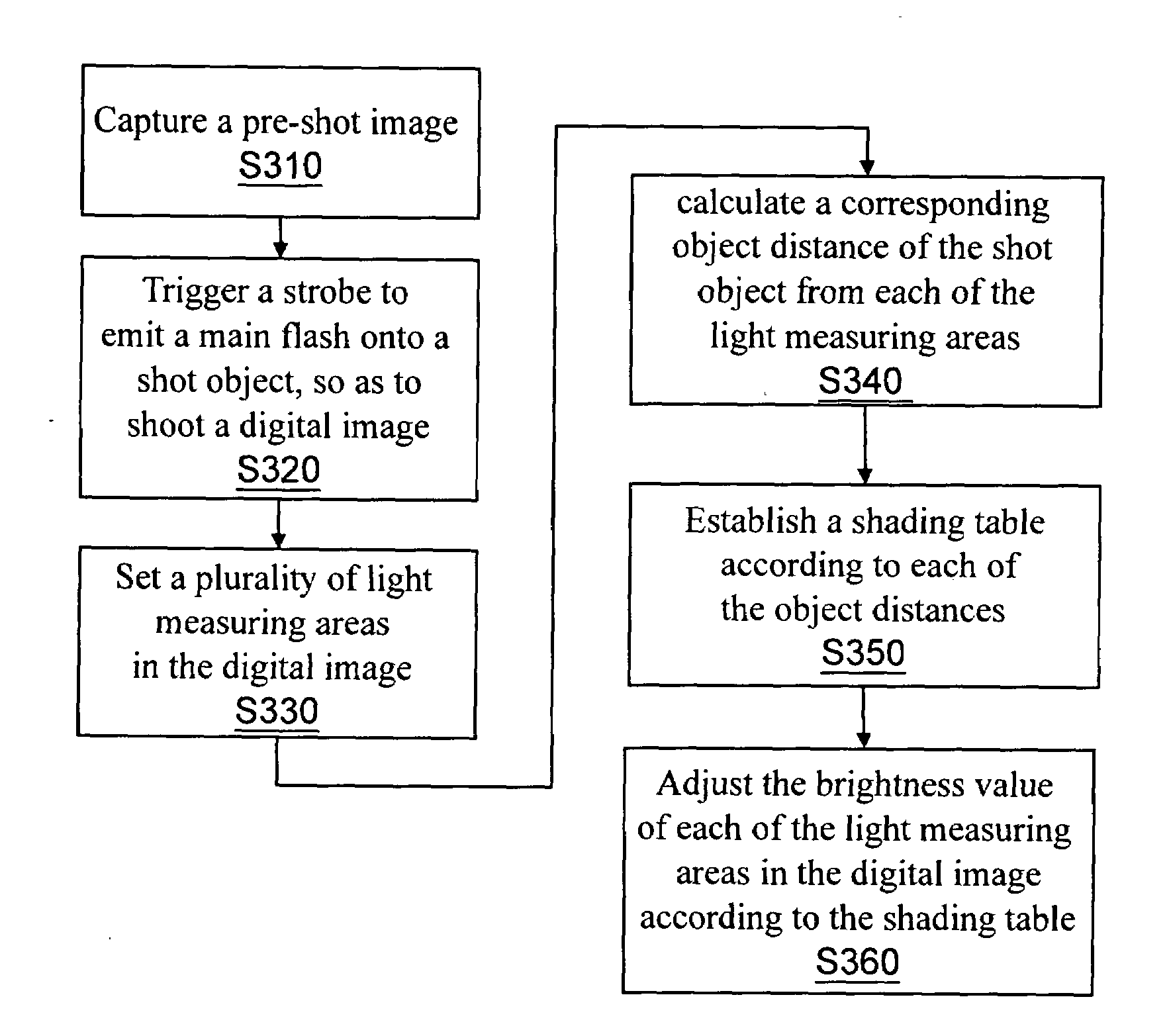
A digital image capture device and a brightness correction method thereof are described. The digital image capture device is adapted to correct the brightness value of a shot object in a digital image through the compensation of a strobe during shooting. The method includes setting a shooting magnification of the digital image capture device to the shot object; capturing a pre-shot image at least including the image of the shot object; triggering a strobe to emit a main flash onto the shot object, so as to shoot a digital image; setting a plurality of light measuring areas in the digital image; calculating a corresponding object distance of the shot object from each of the light measuring areas; establishing a shading table according to each of the object distances; and loading the shading table to adjust the brightness value of each of the light measuring areas in the digital image.

Description

CROSS-REFERENCE TO RELATED APPLICATIONS[0001]This non-provisional application claims priority under 35 U.S.C. § 119(a) on Patent Application No(s). 097149268 filed in Taiwan, R.O.C. on Dec. 17, 2008 the entire contents of which are hereby incorporated by reference.BACKGROUND OF THE INVENTION[0002]1. Field of Invention[0003]The present invention relates to a digital image capture device and a brightness correction method thereof, and more particularly to a method for correcting the brightness value of a shot object at different distances and a digital image capture device thereof.[0004]2. Related Art[0005]With the development of digital cameras, photography is no longer an expensive consumption. Users may shoot desired images at will to record a memorial moment or scene. Due to physical properties, the lens set in the digital image capture device may cause the problem of non-uniform brightness distribution during the imaging of the shot object under the light source. In other words, ...

Claims


Application Information

Patent Timeline
IPC IPC(8): H04N9/68
CPCH04N5/2351H04N5/243H04N5/2354H04N23/71H04N23/74H04N23/76
Inventor CHOU, CHAN-MINLU, CHUNG-PIN
Owner ALTEK CORP
Learn More