

RFID authentication architecture and methods for RFID authentication
- Summary
- Abstract
- Description
- Claims
- Application Information
AI Technical Summary
Benefits of technology
Problems solved by technology
Method used
Image

Examples
Embodiment Construction
.”
BRIEF DESCRIPTION OF THE DRAWINGS
[0031]Features, aspects, and embodiments are described in conjunction with the attached drawings, in which:
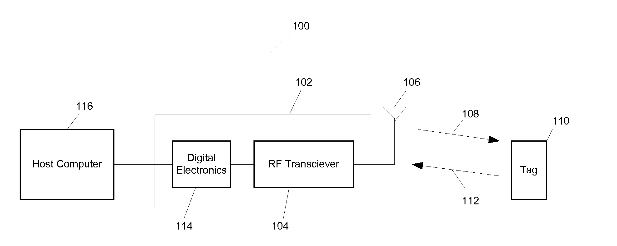
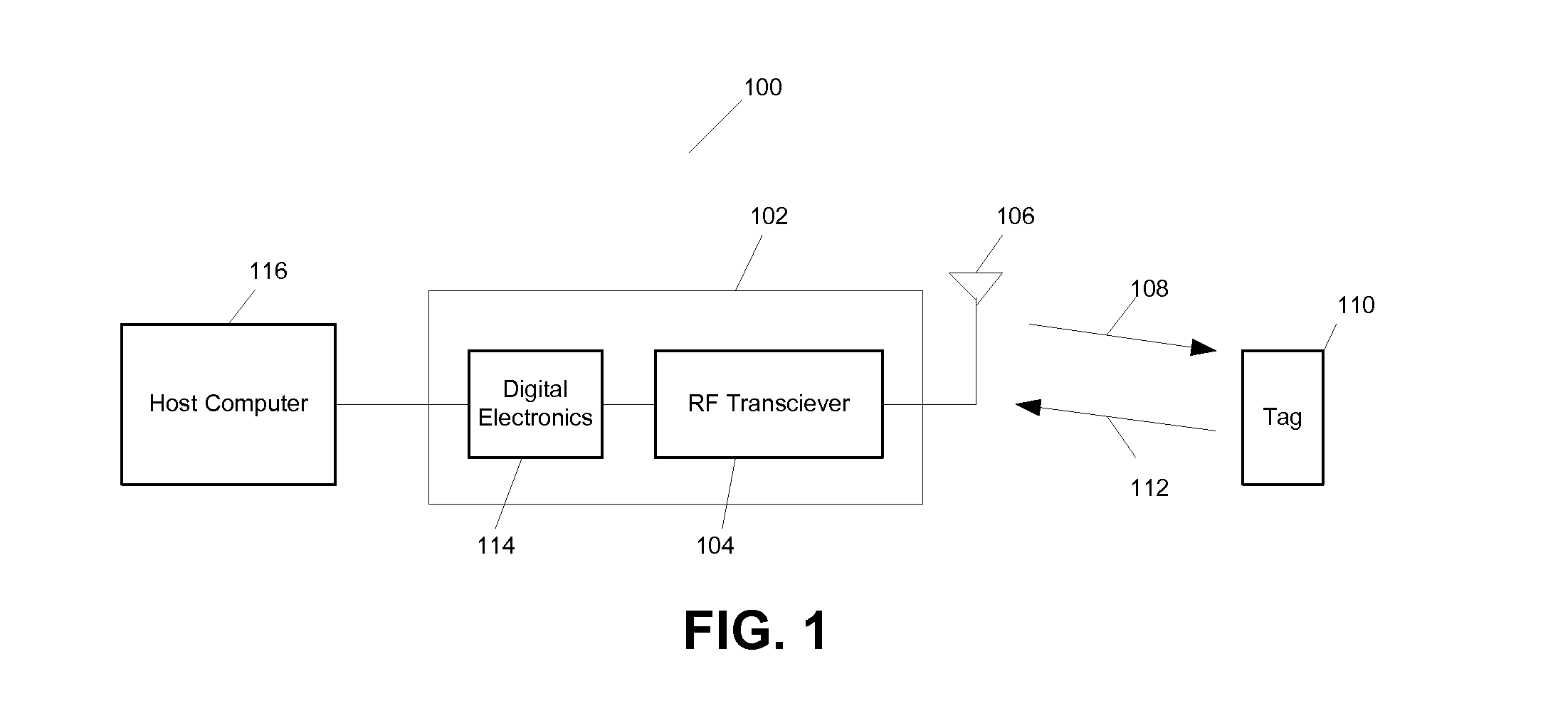
[0032]FIG. 1 is a diagram illustrating an exemplary RFID system;
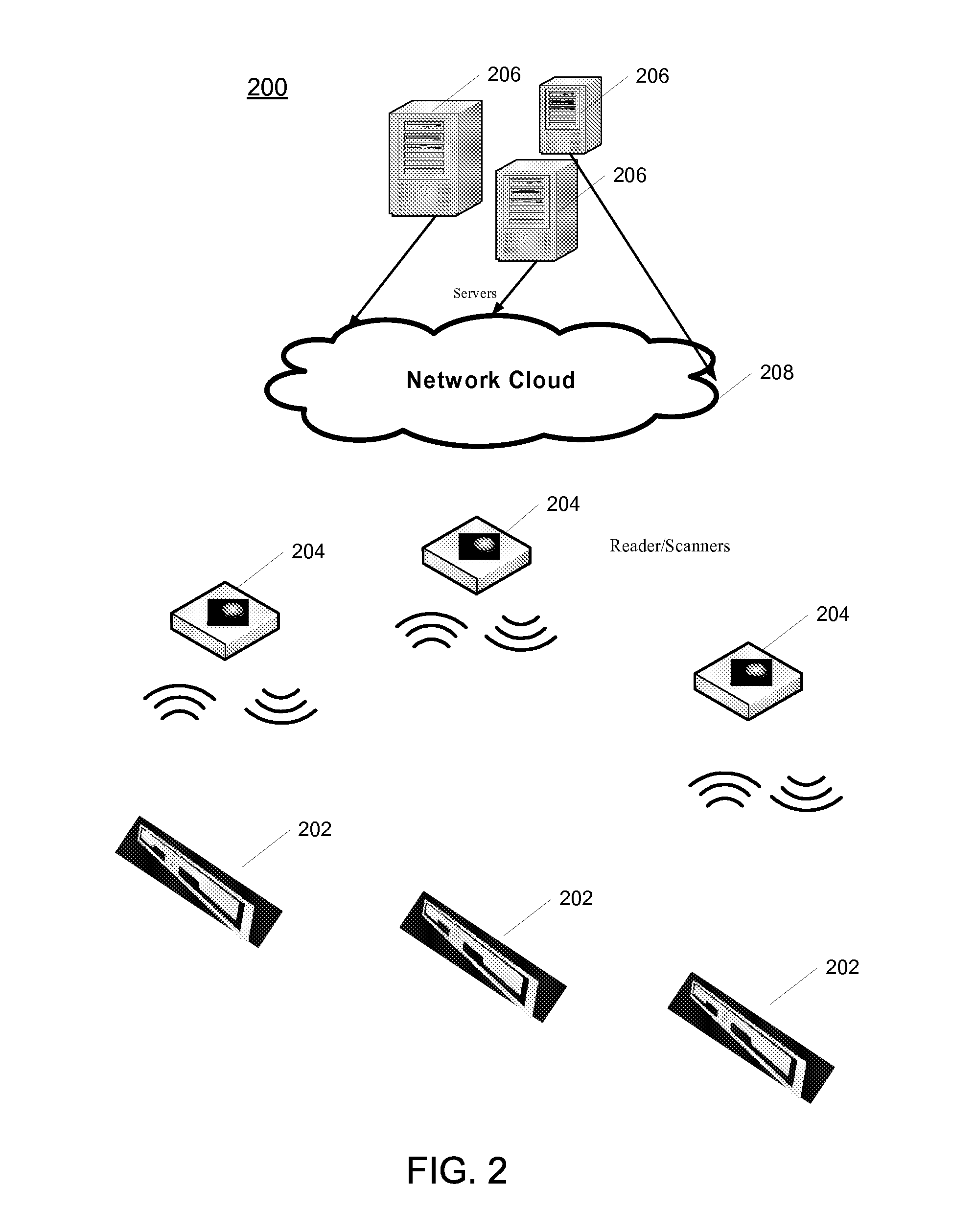
[0033]FIG. 2 is a diagram illustrating an RFID system in accordance with one embodiment;
[0034]FIG. 3 is a diagram illustrating an example RFID tag circuit that can be used in the system of FIG. 2 in accordance with one embodiment;
[0035]FIG. 4 is a diagram illustrating a PRSG that can be used in the circuit of FIG. 3 in accordance with one embodiment;
[0036]FIG. 5 is a flow chart illustrating an example method for mutual authentication between a reader and a tag in the system of FIG. 2 in accordance with one embodiment;
[0037]FIG. 6 is a flow chart illustrating certain steps of the process of FIG. 5 in more detail and in accordance with one embodiment; and
[0038]FIG. 7 is a diagram illustrating another example embodiment of the RFID tag circuit of FIG. 3.
[0039]FIG. 8 is a diagram illu...
PUM
 Abstract
Description
Claims
Application Information