Recording apparatus and recording method

a recording apparatus and recording method technology, applied in the field of recording apparatus, can solve the problems of paper jam, reduce the conveying resistance of the recording medium, and gaps should not be eliminated, so as to improve the accuracy of ink landing positions, and improve the quality of recording

Inactive Publication Date: 2010-06-17
CANON KK
View PDF12 Cites 25 Cited by
  • Summary
  • Abstract
  • Description
  • Claims
  • Application Information

AI Technical Summary

Benefits of technology

[0020]The present invention provides a recording apparatus in which the accuracy of ink landing positions can be improved during skew at the beginning of a paper feeding operation and even during high-frequency skew generated after the skew is settled, as well as a recording method for the same. In particular, the present invention provides a recording apparatus capable of high-quality recording by improving the accuracy of ink landing positions relative to a recording medium, as well as a printing method for the same.

Problems solved by technology

However, if the conveying force at the nip is strong, the skew of the recording medium P is not settled, so that the recording medium P is continuously skewed, causing a paper jam.
However, to reduce the conveying resistance of the recording medium P, these gaps should not be eliminated.
In particular, high-quality printing using a plurality of long inkjet recording heads is affected by even high-frequency skew generated after the first skew is settled.
Therefore, the configuration using a plurality of long recording heads has the problem that the skew induces the displacement of ink landing positions among the parallel nozzle trains, so that high-quality images cannot be formed.
However, this configuration is required to reduce the skew more because when the recording medium is skewed, a phenomenon in which the gaps between the individual chips change to generate alternate white and black stripes on the recording surface of the recording medium is caused depending on the amount of skew.
In general, the amount of widthwise displacement of the recording medium p when the recording medium P is skewed must be held within ±20 μm or less, which is difficult to achieve with the present configuration of the conveying mechanism.

Method used


Image

  • Recording apparatus and recording method
  • Recording apparatus and recording method
  • Recording apparatus and recording method

Examples


first embodiment

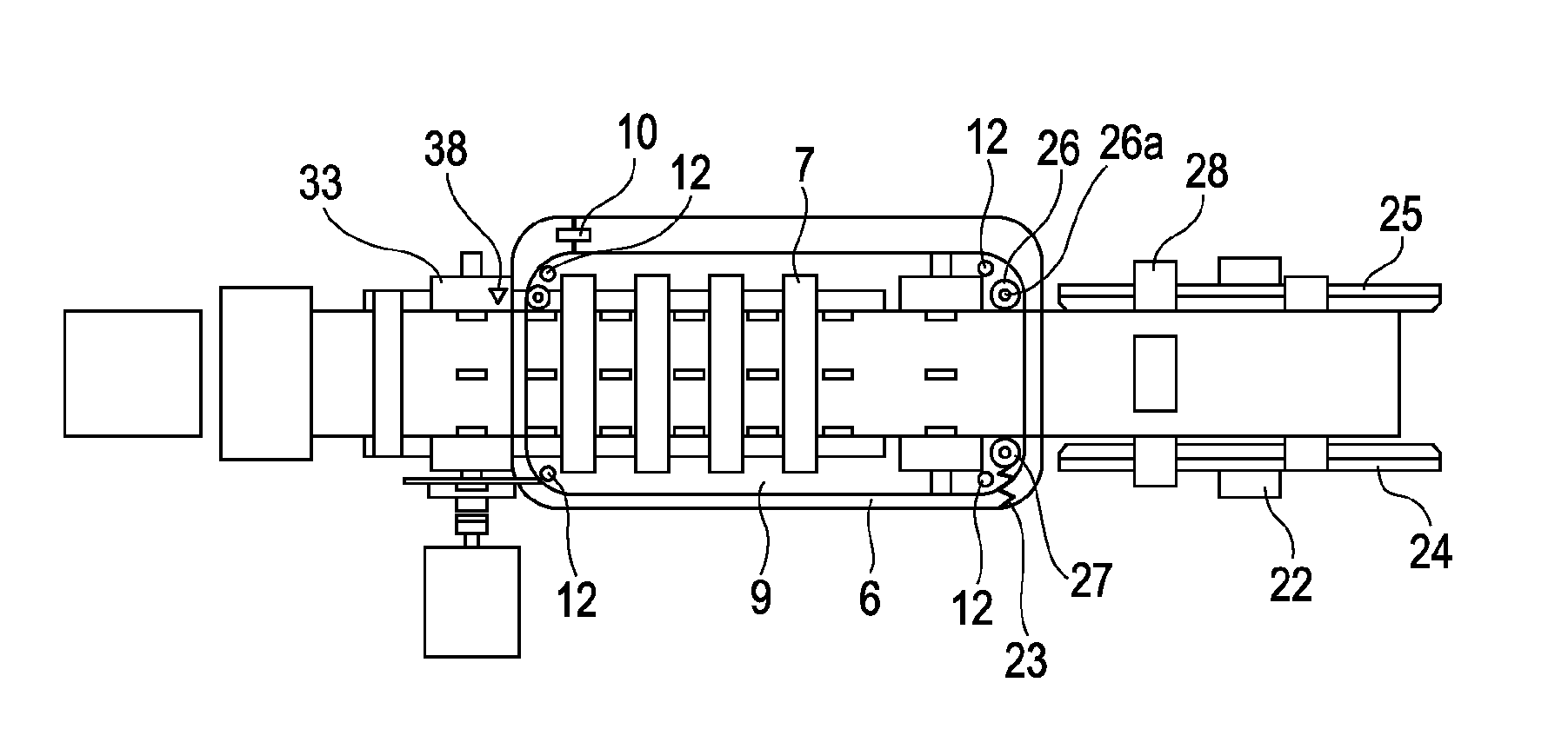
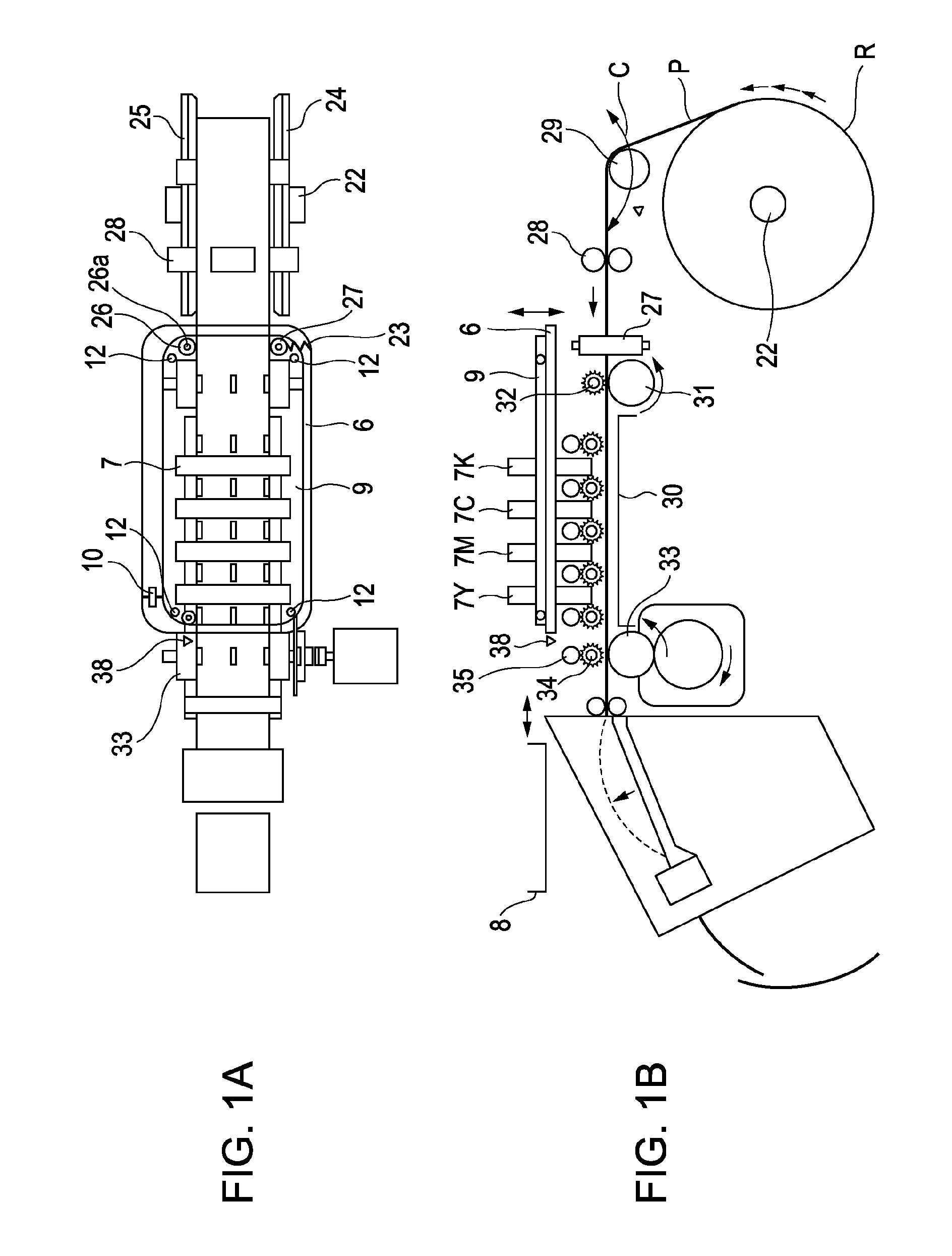
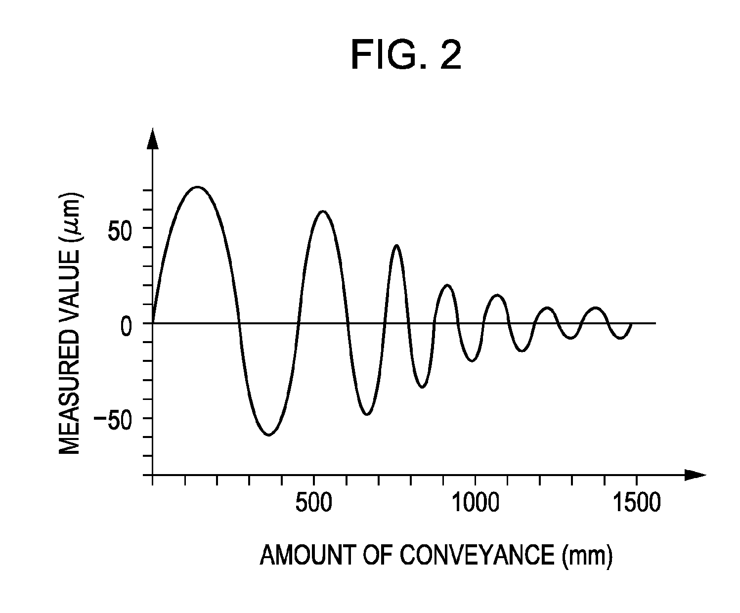
[0052]FIGS. 1A and 1B are diagrams showing an image forming apparatus of the first embodiment. FIG. 1A is a plan view and FIG. 1B is a sectional view. FIG. 2 is a graph showing the measurements of skew generated when a recording medium is conveyed.

[0053]As shown in FIGS. 1A and 1B, the roll R that is a roll of the recording medium P is held on the feed rotating member 22. The recording medium P drawn from the roll R is conveyed to the nip between a conveying roller 31 and a driven roller 32. A loop detection flag 29 gives a fixed tension to the recording medium P between the roll R and a feed roller pair 28.

[0054]A platen 30 is provided at a position facing a plurality of recording heads 7 (7Y, 7M, 7C, and 7K) serving as a recording unit, downstream of the conveying roller 31 and the driven roller 32 serving as a conveying unit. The recording medium P passes directly under the recording heads 7 along the platen 30 and is conveyed to a driving roller 33.

[0055]The long recording heads...

second embodiment

[0084]Next, referring to FIGS. 6A to 6C, a configuration example in which a diagonal feed roller is provided to control the skew of the recording medium P according to another embodiment will be described.

[0085]As shown in FIG. 6A, a diagonal feed roller 40 in which the axial direction of the rotation axis is disposed at an angle with respect to the conveying direction is provided downstream of the loop detection flag 29 in the conveying direction of the recording medium P. The diagonal feed roller 40 is disposed upstream of the reference roller 26. The diagonal feed roller 40 conveys the recording medium P in a direction skewed with respect to the conveying direction while preventing a decrease in the conveying accuracy and unstable occurrence of skew in the recording medium P due the upstream loop. In this embodiment, the diagonal feed roller 40 is disposed such that the axial direction of the rotation axis thereof is at an angle of about seven degrees with respect to the widthwis...


PUM


Abstract

A recording apparatus that performs recording by ejecting ink onto a recording medium from a plurality of recording heads include a conveying roller that conveys the recording medium that is continuously fed; the plurality of recording heads arranged in the conveying direction of the conveying roller; a skew sensor that detects the amount of displacement of the position of the recording medium skewed in the widthwise direction perpendicular to the conveying direction relative to the recording heads when the recording medium is skewed with respect to the conveying direction; and an angle adjusting mechanism that rotates the recording heads relative to the recording medium on the basis of the amount of displacement detected by the skew sensor.

Description

BACKGROUND OF THE INVENTION[0001]1. Field of the Invention[0002]The present invention relates to a recording apparatus that records on a recording medium, such as roll paper, by ejecting ink thereon, as well as a recording method for the same. In particular, the present invention relates to a recording apparatus and method capable of recording under little influence of skew of the recording medium.[0003]2. Description of the Related Art[0004]In general, some of image forming apparatuses, in particular, color-image forming apparatuses, are capable of high-volume printing at a time using roll paper to record a plurality of recording sheets. Known examples of this type of recording apparatus that record using roll paper adopt a dry silver-salt system and an inkjet system. A roll of recording medium, such as long recording paper, is generally called roll paper. In the following description, the rolled portion of the roll paper is referred to as a roll, and a sheet-like portion drawn fro...

Claims


Application Information

Patent Timeline
Patent Type & Authority Applications(United States)
IPC IPC(8): G03G15/00
CPCB41J2/515G03G2215/00565B41J25/001B41J2/2146
Inventor MATSUMOTO, TADASHINAOI, MASAAKIKIYAMA, KOTANINOMIYA, TAKAYUKI
Owner CANON KK
Why Eureka
Try Eureka