Optical sensor and methods for measuring molecular binding interactions
What is Al technical title?
Al technical title is built by PatSnap Al team. It summarizes the technical point description of the patent document.
a molecular binding interaction and optical sensor technology, applied in the field of optical sensors, can solve the problems of high cost of spr sensors, impracticality of many applications, high cost of resonant mirror systems,
Inactive Publication Date: 2010-06-17
SILICON KINETICS
View PDF4 Cites 23 Cited by
Summary
Abstract
Description
Claims
Application Information
AI Technical Summary
This helps you quickly interpret patents by identifying the three key elements:
Problems solved by technology
Method used
Benefits of technology
Benefits of technology
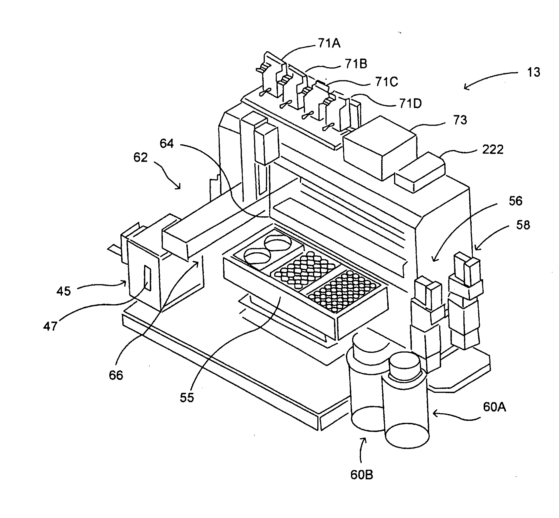
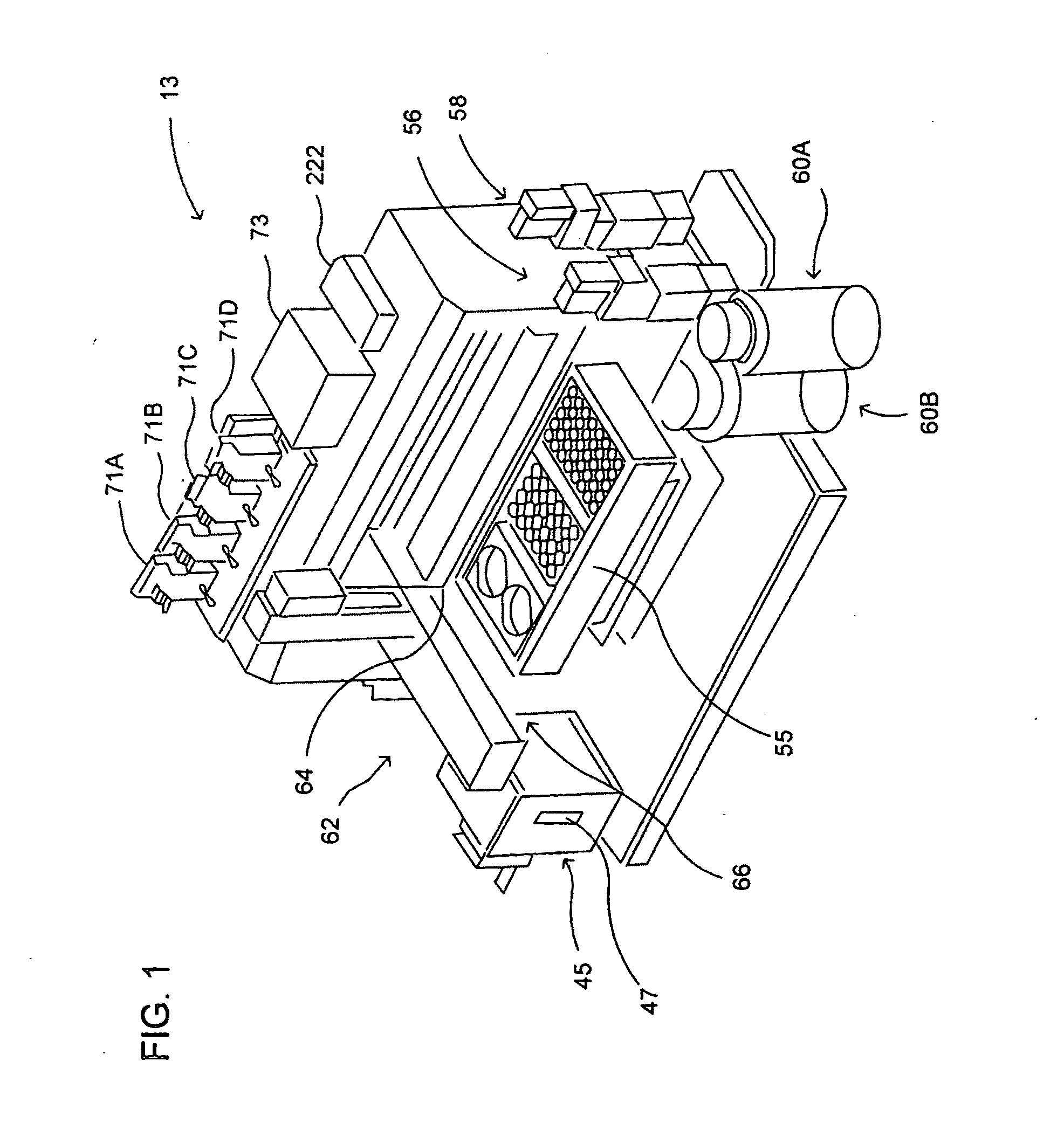
[0010]This invention provides methods and devices for the measurement of molecular binding interactions. Ligands are immobilized within pores of a porous silicon interaction region produced within a crystalline silicon substrate and analytes diluted in a buffer fluid are flowed over the porous silicon region. Binding reactions occur after analyte molecules diffuse closely enough to the ligands to become bound. Both ligands and analytes are delivered by computer controlled robotic fluid flow control techniques to the porous silicon interaction regions through microfluidic flow channels. The association and subsequent disassociation reactions are observed optically. In preferred embodiments the observation is accomplished with a white light source and thin film interference techniques with spectrometers arranged to detect changes in indices of refraction in the region where the binding and disassociation reactions occur. In a prototype unit designed as tested by applicants, four interaction regions are provided each wit
Problems solved by technology
These SPR sensors are typically very expensive.
As a result, the technique is impractical for many applications.
Like SPR sensors, resonant mirror systems are expensive and impractical for many applications.
In addition to the optical biosensors discussed above, scientists perform kinetic binding
Method used
Image
Click on the blue label to locate the original text in one second.
Reading with bidirectional positioning of images and text.
Examples
example demonstrating
Chemical Features of Preferred Embodiments
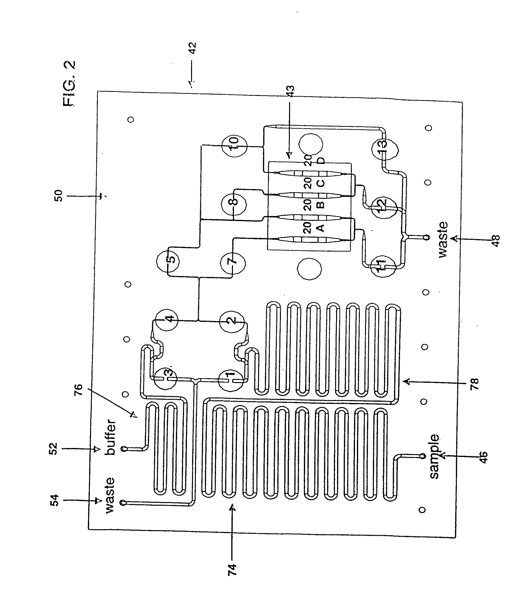
[0134]In addition to providing the key component for the optical measurement subsystem, the porous section observation regions 20A, B, C and D also serve as three-dimensional scaffolds to immobilize specific molecules. The regions provide a very large surface area in the form of cylindrical walls of pores 90. Ligand molecules are attached, or bound, to the pore walls 90 by the use of specific linker molecules. The linker molecules are attached to the pore walls by the use of surface chemistry, and the ligand molecules are then attached to the linker molecules.
[0135]FIGS. 9A-9F show a specific set of molecular interactions involved in an example of an application of the present invention. FIGS. 9A and 9B show steps a) and b) of a preferred method for immobilizing ligand protein molecules to the walls of pores 90. Steps a) and b) preferably are performed in a laboratory independent of the device shown in FIG. 1 and steps 9C-9F take place withi...
PUM
Abstract
Optical sensor for the measurement of molecular binding interactions. Preferred embodiments provide real-time measurements of kinetic binding and disassociation of molecules including binding and disassociation of protein molecules with other protein molecules and with other molecules. In preferred embodiments ligands are immobilized within pores of a porous silicon interaction region produced in a silicon substrate, after which analytes suspended in a fluid are flowed over the porous silicon region. Binding reactions occur when analyte molecules diffuse closely enough to the ligands to become bound. In preferred embodiments both ligands and analytes are delivered by computer controlled robotic fluid flow control techniques to the porous silicon interaction regions through microfluidic flow channels.
Description
[0001]This application claims the benefit of provisional patent application Ser. Nos. 60 / 962,652, 60 / 962,616, 60 / 962,664, 60 / 962,756, 60 / 962,675, 60 / 962,669 and 60 / 962,644 all filed Jul. 30, 2007 and provisional patent application Ser. No. 61 / 127,910, filed May 15, 2008 and is a continuation in part of Ser. No. 11 / 180,349 filed Jul. 13, 2005, Ser. No. 10 / 631,592 filed Jul. 30, 2003 and Ser. No. 10 / 616,251 filed Jul. 8, 2003. This invention relates to optical sensors and in particular to optical biosensors.BACKGROUND OF THE INVENTION[0002]The prior art includes a wide variety of optical sensors. An optical biosensor is an optical sensor that incorporates a biological sensing element. In recent years optical biosensors have become widely used for sensitive molecular binding measurements.Surface Plasmon Resonance[0003]An optical biosensor technique that has gained increasing importance over the last decade is the surface plasmon resonance (SPR) technique. This technique involves the me...
Claims
Application Information
Patent Timeline
Application Date:The date an application was filed.
Publication Date:The date a patent or application was officially published.
First Publication Date:The earliest publication date of a patent with the same application number.
Issue Date:Publication date of the patent grant document.
PCT Entry Date:The Entry date of PCT National Phase.
Estimated Expiry Date:The statutory expiry date of a patent right according to the Patent Law, and it is the longest term of protection that the patent right can achieve without the termination of the patent right due to other reasons(Term extension factor has been taken into account ).
Invalid Date:Actual expiry date is based on effective date or publication date of legal transaction data of invalid patent.
