Artificial teeth

a technology of artificial teeth and teeth, applied in the field of artificial teeth, can solve the problems of difficult to arrange adjacent teeth in an appropriate positional relation, difficult to arrange adjacent teeth in specified positions to the upper and lower jaws, etc., and achieve the effect of easy adjustment and easy arrangemen

Inactive Publication Date: 2010-06-17
SHOFU INC
View PDF32 Cites 11 Cited by
  • Summary
  • Abstract
  • Description
  • Claims
  • Application Information

AI Technical Summary

Benefits of technology

[0027]Thus, with the teeth arranged on the maxillary plate and the mandibular plate, only by positioning the arrangement confirmation sheets to the vestibular lateral surface or the oral lateral surface, it can be easily checked whether the teeth are arranged in normal state or not. If there is an error in arrangement, it can be adjusted easily. The teeth may be arranged easily without requiring advanced skills and experiences.
[0028]Acco...

Problems solved by technology

In particular, it was difficult to arrange the adjacent teeth in an appropriate positional relation.
It was, however, extremely difficult to arrange the teeth in specified positions to the upper and lower jaws, or arrange the adjacent teeth in specified positions.
However, in the artificial molar teeth of JP-A-2002-177301, since the positions of the c...

Method used


Image

  • Artificial teeth
  • Artificial teeth
  • Artificial teeth

Examples


first embodiment

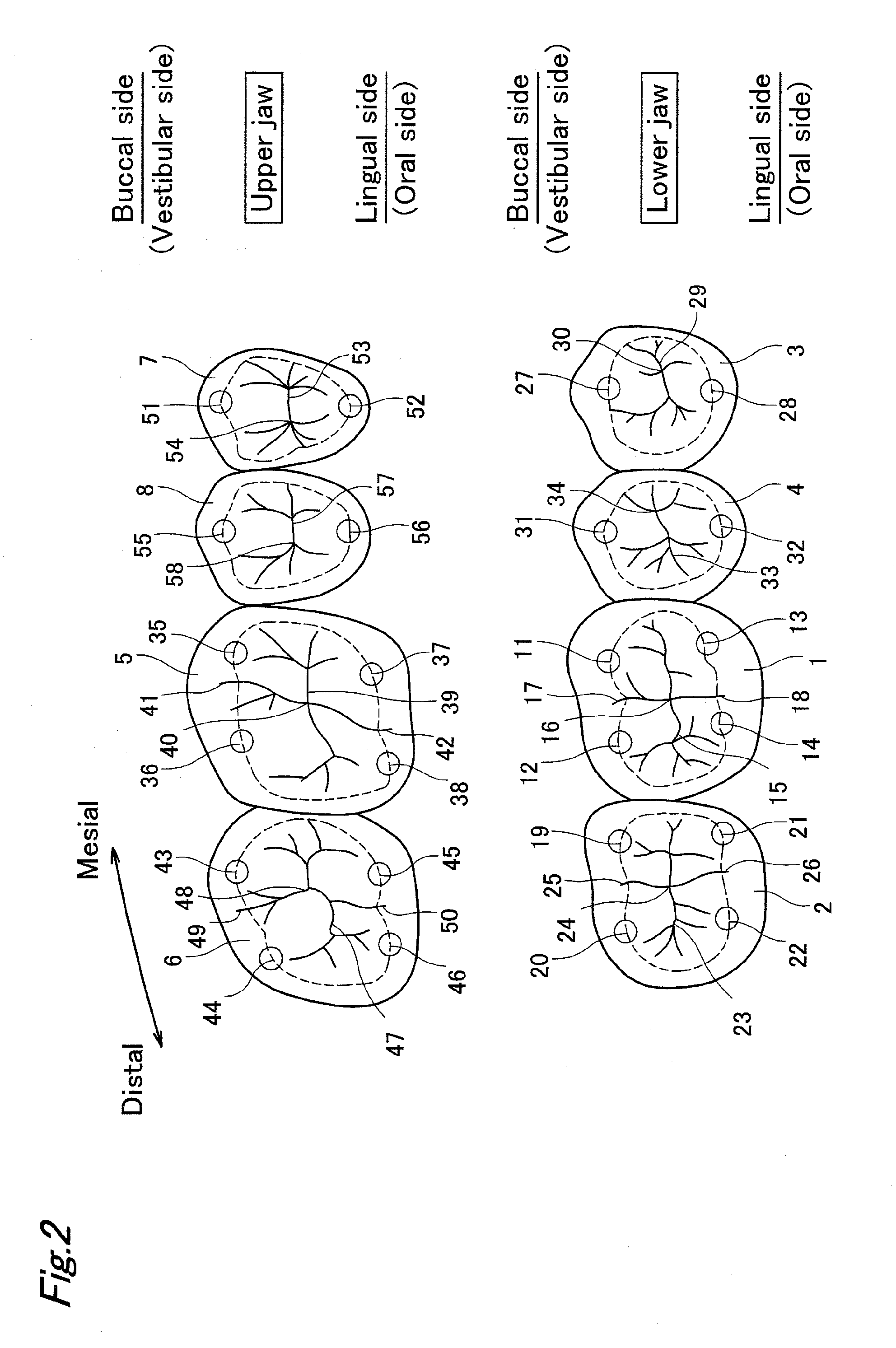
[0041]The present invention relates to techniques of making artificial teeth as a dental prosthetic appliance of denture. A first embodiment relates to techniques to be used in making artificial molar teeth. The artificial molar teeth include a first molar tooth, a second molar tooth, a first premolar tooth, and a second premolar tooth, and preferably two or more adjacent teeth thereof may be combined, and more preferably all four adjacent teeth may be combined. Moreover, four teeth including upper and lower mutually opposing antagonist first molar teeth, antagonist second molar teeth, antagonist first premolar teeth, and antagonist second premolar teeth are preferred, and more preferably eight teeth of all upper and lower opposing molar teeth may be combined.

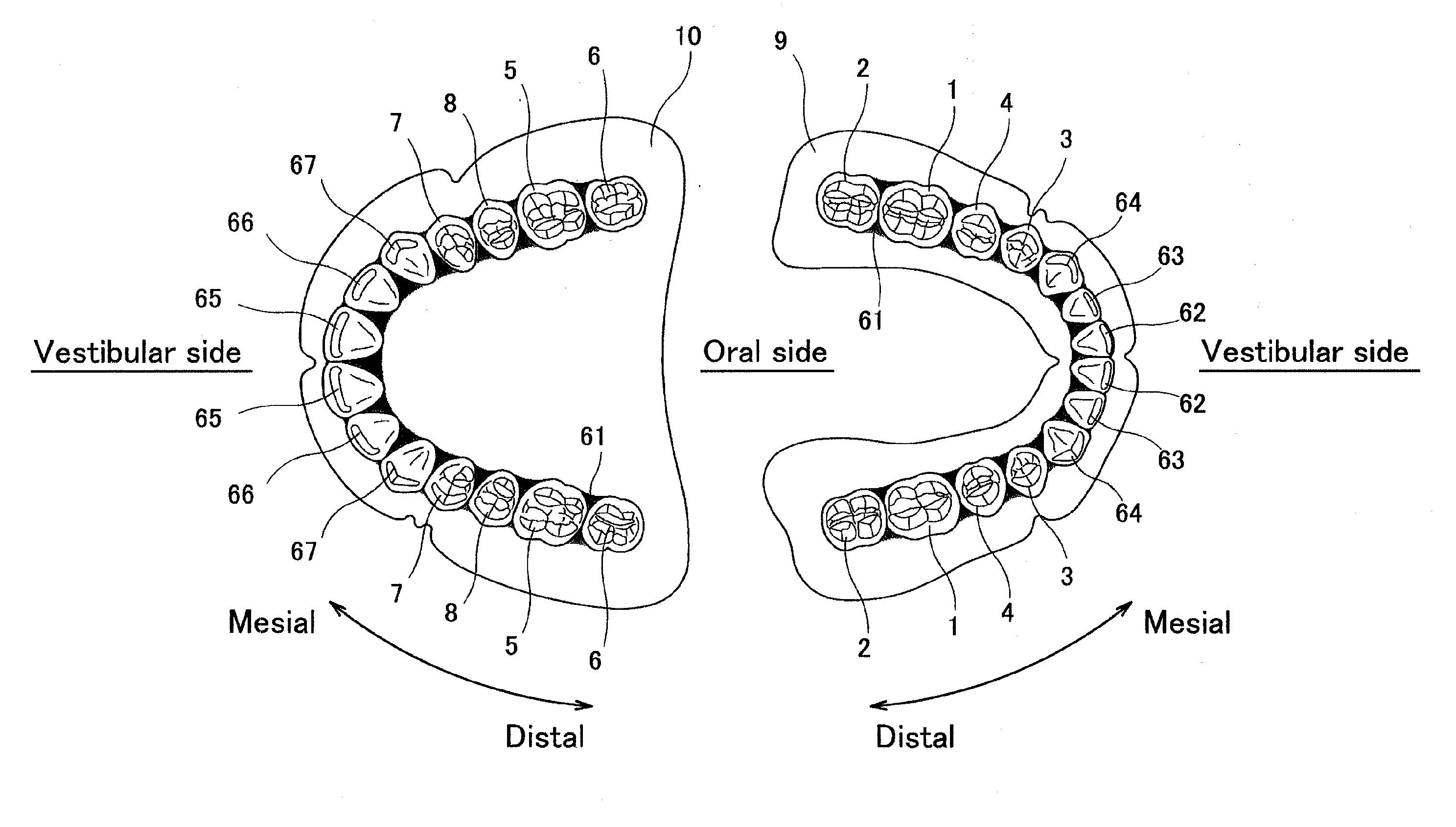
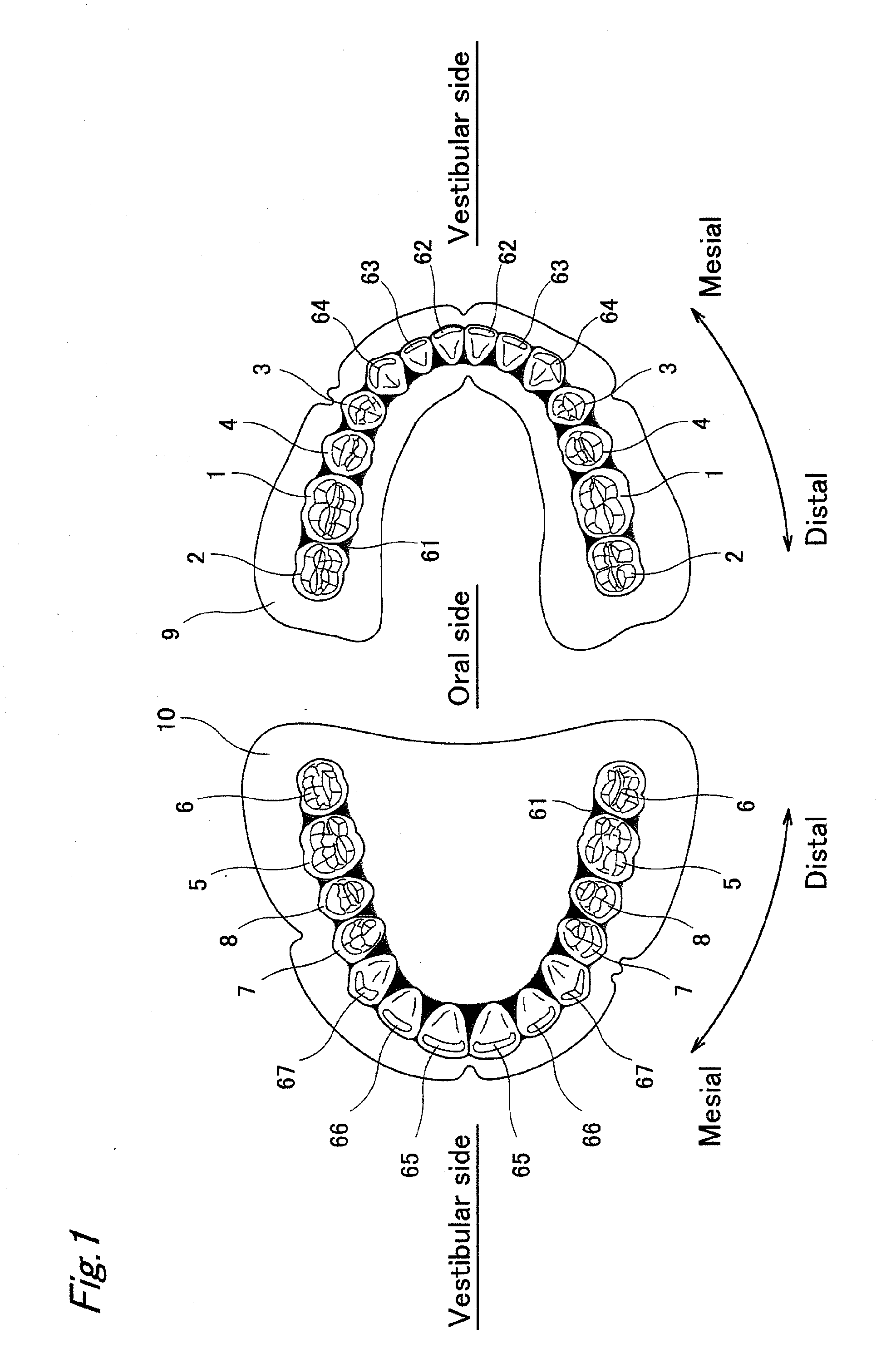
[0042]In the following description, a direction approaching anterior teeth is called a mesial side, and an opposite departing direction is called a distal side. In addition, the inside of an oral cavity is called a lingual side...

third embodiment

[0080]More specifically, the artificial teeth 1 to 8, 62 to 67 in the third embodiment are provided with indication lines 71 extended in the apical-cervical direction by coloring the vestibular lateral side as arrangement direction indication parts. As shown in FIG. 7, when covered in a central occlusion position, a part of the vestibular side of the mandibular teeth 1 to 4, 62 to 64 is covered with the maxillary teeth 5 to 8, 65 to 67. After the arrangement, moreover, the wax (the wax rim of the temporary plate) is replace by a resin plate (a resin-made plate). Accordingly, in order that the indication lines 71 may not be concealed in this covered state or may not be concealed by the wax, the indication lines 71 are extended linearly from the apical side edge to the cervical side edge as seen from the vestibular side. Being extended linearly means, herein, either one straight line, or a line containing plural points extended intermittently (e.g., broken line). In the embodiment, th...


PUM


Abstract

The invention provides artificial teeth arranged in plates attached in an oral cavity as a dental prosthetic appliance, in which arrangement direction indication parts showing a directivity of arrangement in the plates extending in an apical-cervical direction or in a mesiodistal direction are provided at a vestibular side or an oral side. The arrangement direction indication parts extending in the apical-cervical direction are positioned linearly as seen from the vestibular side in a occluded state of mandibular teeth and maxillary teeth. The arrangement direction indication parts extending in the mesiodistal direction are positioned linearly as seen from the vestibular side in the state arranged in plates. The artificial teeth are arranged at an appropriate position according to an oral environment of each patient, without requiring advanced skills and experiences.

Description

BACKGROUND OF THE INVENTION[0001]1. Field of the Invention[0002]The present invention relates to artificial teeth which can be arranged easily when making a dental prosthetic appliance and are easy in mastication when wearing it as dentures.[0003]2. Description of the Related Art[0004]Arrangement of artificial molar teeth when making a dental prosthetic appliance required advanced skills and experiences. In particular, it was difficult to arrange the adjacent teeth in an appropriate positional relation. Specifically, in dentures, the artificial teeth to be arranged in six degrees of freedom (position and angle) must be arranged at specified positions, and the dentures must be made for individual patients. It was, however, extremely difficult to arrange the teeth in specified positions to the upper and lower jaws, or arrange the adjacent teeth in specified positions. In conventional artificial teeth, accordingly, in order to obtain an ideal mastication, it was required to grind large...

Claims


Application Information

Patent Timeline
IPC IPC(8): A61C13/08
CPCA61C13/0003A61C13/01A61C13/10A61C13/097A61C13/12A61C13/08
Inventor KADOBAYASHI, YUSEIFUJII, TOSHIHIDE
Owner SHOFU INC
Why Eureka
Try Eureka