Terminal

a technology of terminals and contacts, applied in the field of terminals, to achieve the effect of reducing insertion force, reducing insertion force, and reducing workload for workers

Active Publication Date: 2010-06-17
YAZAKI CORP
View PDF8 Cites 17 Cited by
  • Summary
  • Abstract
  • Description
  • Claims
  • Application Information

AI Technical Summary

Benefits of technology

[0020]As explained above, the terminal according to the present invention described in claim 1 is provided with the plurality of elastic pieces arranged in parallel to each other at an interval along the insertion direction of the insert portion. As the insert portion of the mating terminal enters into the electrical contact portion, the insert portion passes over the elastic pieces one by one, so an elastic restoring force increases little by little, dispersively. Thus, the elastic restoring force generated from the elastic pieces arranged along the insertion direction becomes smaller compared to an elastic restoring force generated instantaneously from the plurality of elastic pieces arranged along a direction perpendicular to the insertion direction. Consequently, the terminal which can reduce the insertion force can be provided.
[0021]Furthermore, by providing the terminal with a reduced insertion force, a workload for a worker can be lightened when inspecting the terminal, so a process for applying grease can be cut off. Thus, the manufacturing cost of the terminal can be reduced.
[0022]As explained above, the terminal according to the present invention described in claim 2 is provided with the elastic pieces arranged so a longitudinal direction thereof is perpendicular to the insertion direction of the insert portion. Each of the elastic pieces is inclined relative to the bottom wall to the insertion direction of the insert portion, where one end of the each elastic piece is arranged adjacent to an inner surface of the bottom wall (arranged to be contacted with the bottom wall). Consequently, when the insert portion is inserted into the electrical contact portion, a top end of the insert portion will not interfere with the elastic pieces. Thus, a risk for detaching a spring member which includes the elastic pieces is lowered, so a failure rate of the terminal can be reduced.
[0023]Furthermore, the terminal according to the present invention is provided with a pair of connecting pieces arranged at both ends of the bottom wall, with a longitudinal direction thereof arranged parallel to the insertion direction of the insert portion. On the other hand, the conventional terminal described above is provided with the pair of connecting pieces arranged at both ends of the bottom wall, with the longitudinal direction thereof being arranged perpendicular to the insertion direction of the insert portion. Thus, for the inventive terminal, contacting area of the top end of the insert portion with each end of the connecting pieces is smaller compared to the conventional terminal. Consequently, the interference between the top end of the insert portion and the connecting pieces becomes small. Thus, a risk for detaching the spring member which includes the connecting pieces is lowered, so the failure rate of the terminal can be reduced.

Problems solved by technology

Furthermore, there was a need for applying grease to reduce the insertion force to lighten the workload, increasing a number of working process.

Method used


Image

  • Terminal
  • Terminal
  • Terminal

Examples


Embodiment Construction

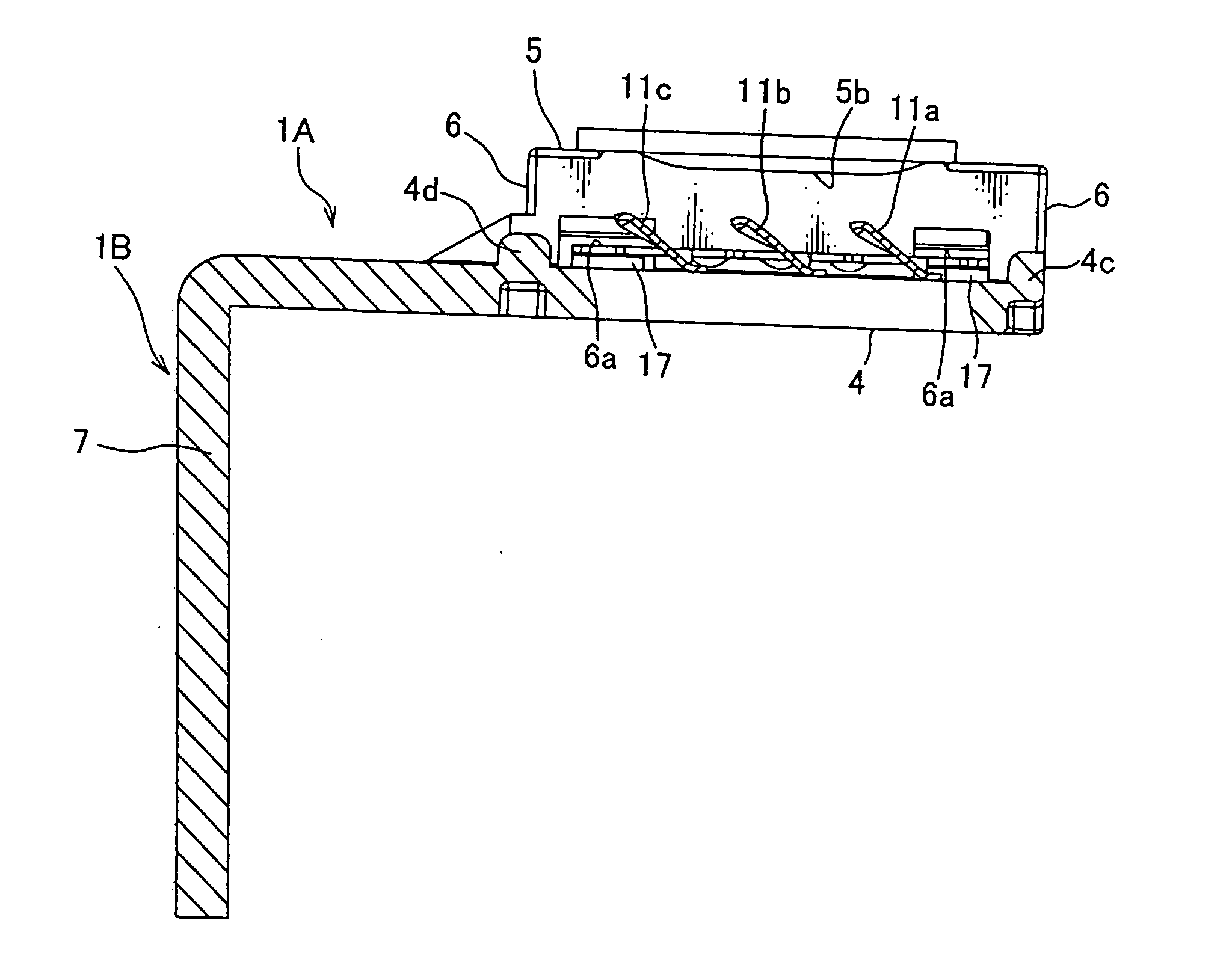
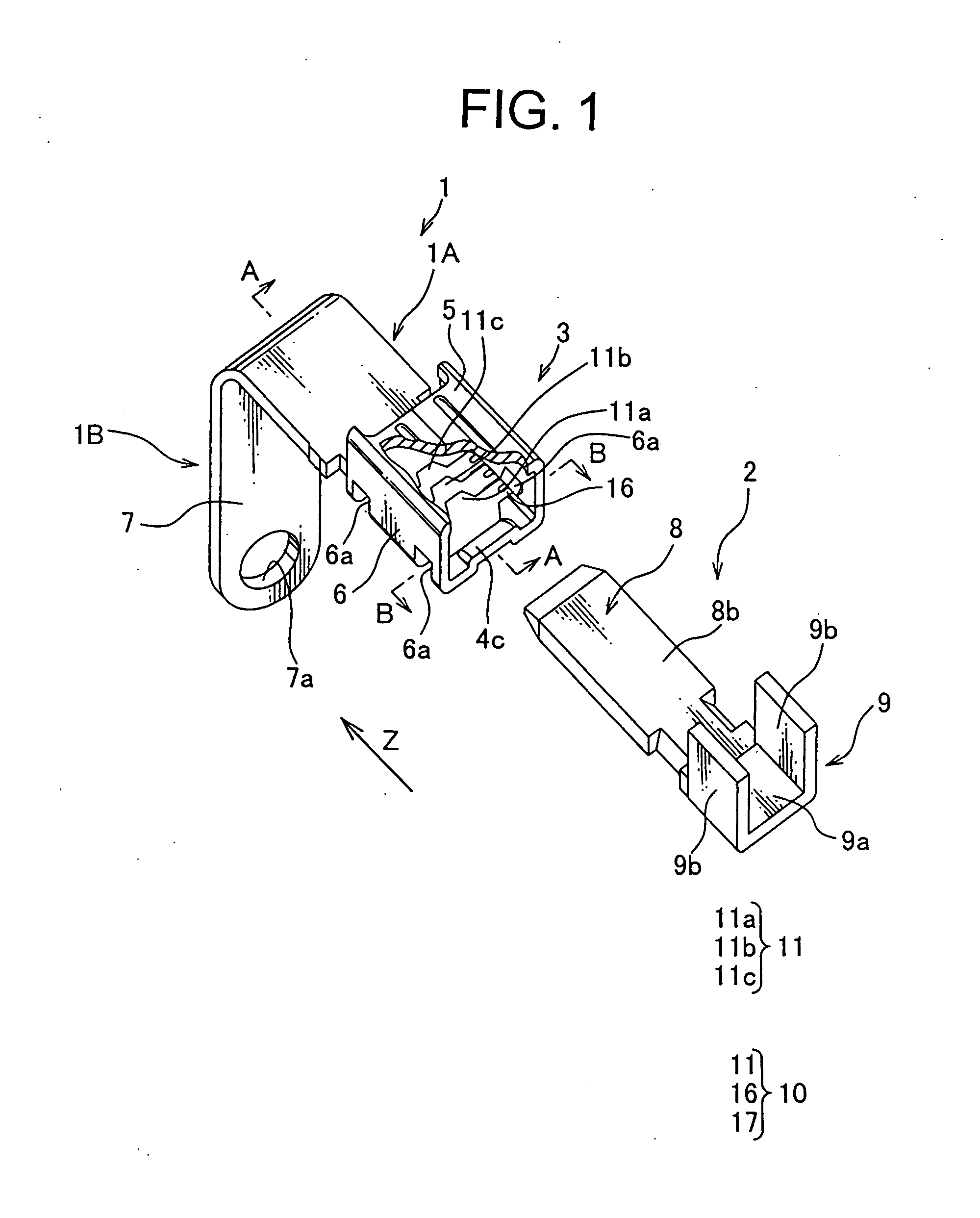
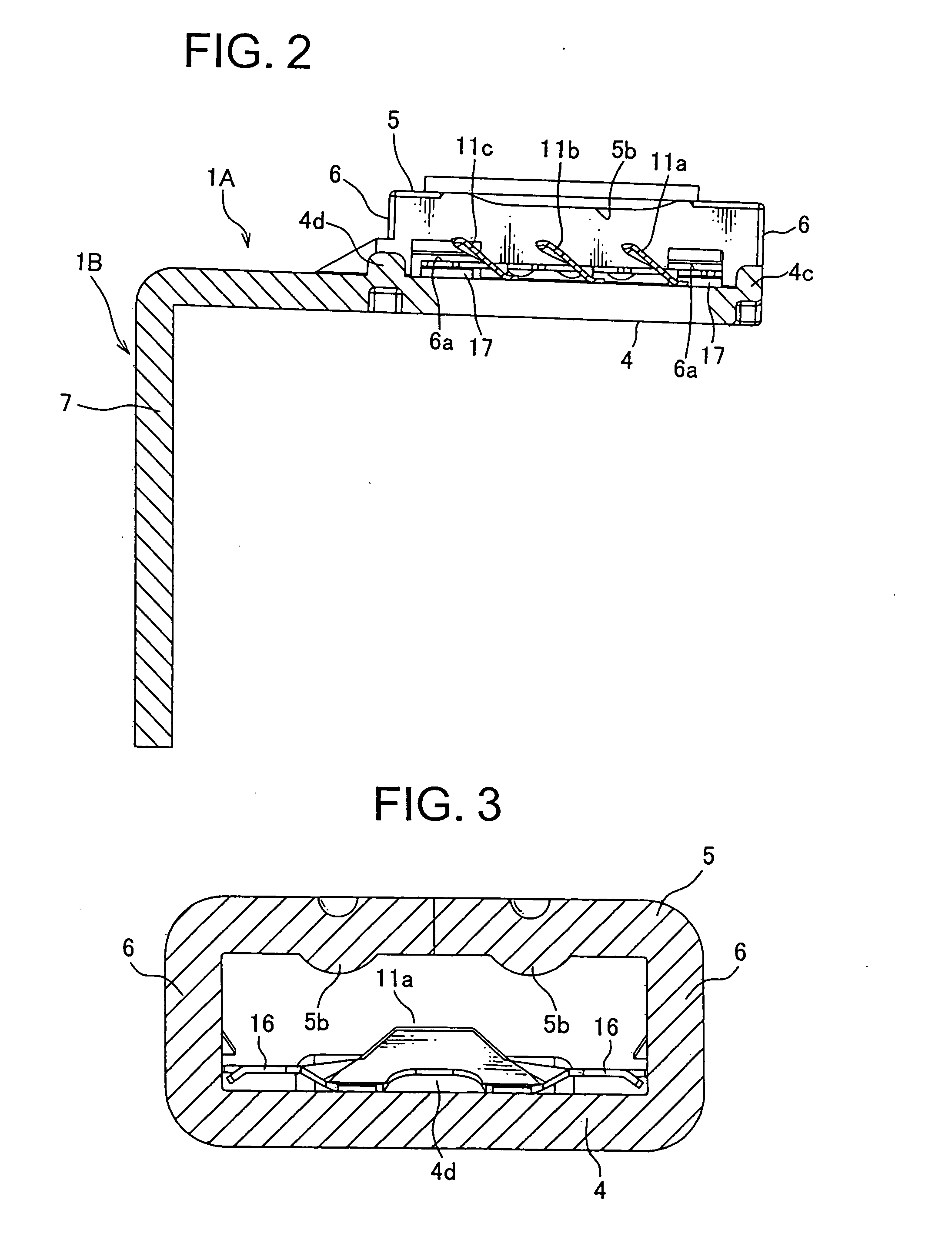
[0030]One embodiment of a terminal according to the present invention will be explained hereinafter in reference to FIGS. 1 to 3. A terminal 1 according to one embodiment of the present invention is used to electrically connect a mating terminal 2 to an electric device via a conductor such as an electric wire, by inserting the mating terminal 2 into the terminal 1.

[0031]The mating terminal 2 is made of conductive plate-shaped sheet metal, and is provided with an insert portion 8 at one end thereof and a connection portion 9 at the other end thereof.

[0032]The insert portion 8 is formed in a plate shape and is formed to be thinner towards the tip thereof, so as to be able to enter into an electrical contact portion 3 of the terminal 1, as shown in FIG. 1. The insert portion 8 has one surface (not shown) and the other surface 8b, which abut on a bottom wall 4 and an upper wall 5 respectively when inserted into the electrical contact portion 3.

[0033]The connection portion 9 of the matin...


PUM


Abstract

A terminal including a tube-shaped electrical contact portion into which an insert portion of a mating terminal is inserted. The electrical contact portion includes: a pair of walls arranged in parallel to each other, which the insert portion is inserted between; and a plurality of elastic pieces provided at one wall of the pair of walls so as to be formed projecting from the one wall to the other wall of the pair of walls, and pushing the insert portion toward the other wall so as to hold the insert portion between the plurality of elastic pieces and the other wall. The plurality of elastic pieces is arranged in parallel to each other at an interval along an insertion direction of the insert portion.

Description

[0001]The Japan Patent Application No. 2008-317795 upon which this patent application is based is hereby incorporated by reference.BACKGROUND OF THE INVENTION[0002]1. Field of the Invention[0003]The present invention relates to a terminal for connecting an electric wire to a connecting terminal of an electrical component such as a bus bar, a relay or a fuse.[0004]2. Description of Related Art[0005]A terminal 101, as shown in Japanese Patent Publication No. 2007-250362, has been used, for example, for a connection between an electric wire and a connecting terminal of an electrical component such as a bus bar, a relay or a fuse. The terminal 101 shown in FIG. 6 includes an electrical contact portion 103 and an electrical connecting portion 105. A plate-like insert portion 110a of a mating terminal 110 is inserted into the electrical contact portion 103, so that the electric wire is electrically connected to the connecting terminal of the electrical component such as the bus bar, the r...

Claims


Application Information

Patent Timeline
Patent Type & Authority Applications(United States)
IPC IPC(8): H01R4/48
CPCH01R13/113H01R4/4881H01R13/187
Inventor KATO, HAJIMEYOSHIOKA, NOBUAKI
Owner YAZAKI CORP
Why Eureka
Try Eureka