Structure improvement of orthopaedic implant

Inactive Publication Date: 2010-06-17
UNITED ORTHOPEDIC CORP
View PDF10 Cites 40 Cited by
  • Summary
  • Abstract
  • Description
  • Claims
  • Application Information

AI Technical Summary

Benefits of technology

[0007]An objective of the present invention is to provide a structure improvement of orthopaedic implant, which comprises a reinforcement inset in a tibial insert and coupled, in a downward direction, to a stem or an offset stem adaptor to drive a sleeve of the reinforcement to project beyond a bottom of the tibial insert for fitting into a groove defined in a tibial baseplate to provide the efficacies of stable coupling, resistance against external forces, prevention of deformation, and extension of lifespan thereby enhancing practicability and inventiveness of the present invention.
[0008]Another objective of the present invention is to provide a structure improvement of orthopaedic implant, wherein a reinforcement is directly set inside a bore defined in a tibial insert, which shows a configuration having an expanded upper section and a reduced lower section, and a sleeve of the reinforcement has a circumferential outer surface that forms threading or is made roughened, thereby providing the efficacies of increasing operation efficiency, providing safety of use, and making a stable coupling and thus enhancing the inventiveness and safety of the present invention.
[0009]A further objective of the present invention is to provide a structure improvement of orthopaedic implant, wherein the components of the orthopaedic implant are of modular designs and suit for difference of individuals and allow for partial replacement to thereby offer the efficacies of being easy to use and reducing costs and thus enhancing the practicability and convenience of the present invention.
[0010]To achi

Problems solved by technology

Due to aging, joints of human beings may suffer wear or degradation caused by long term use or degeneration, leading to pain or incapability of providing proper moving functions, as a consequence of which daily living is affected.
The tibial insert forms thereon a support that constrains the movement between the femural implant and the tibial insert, but it is often made of plastics and is susceptible to fracture caused by long resistance against external forces acting thereon.
Daily activity of human beings

Method used


Image

  • Structure improvement of orthopaedic implant
  • Structure improvement of orthopaedic implant
  • Structure improvement of orthopaedic implant

Examples


Embodiment Construction

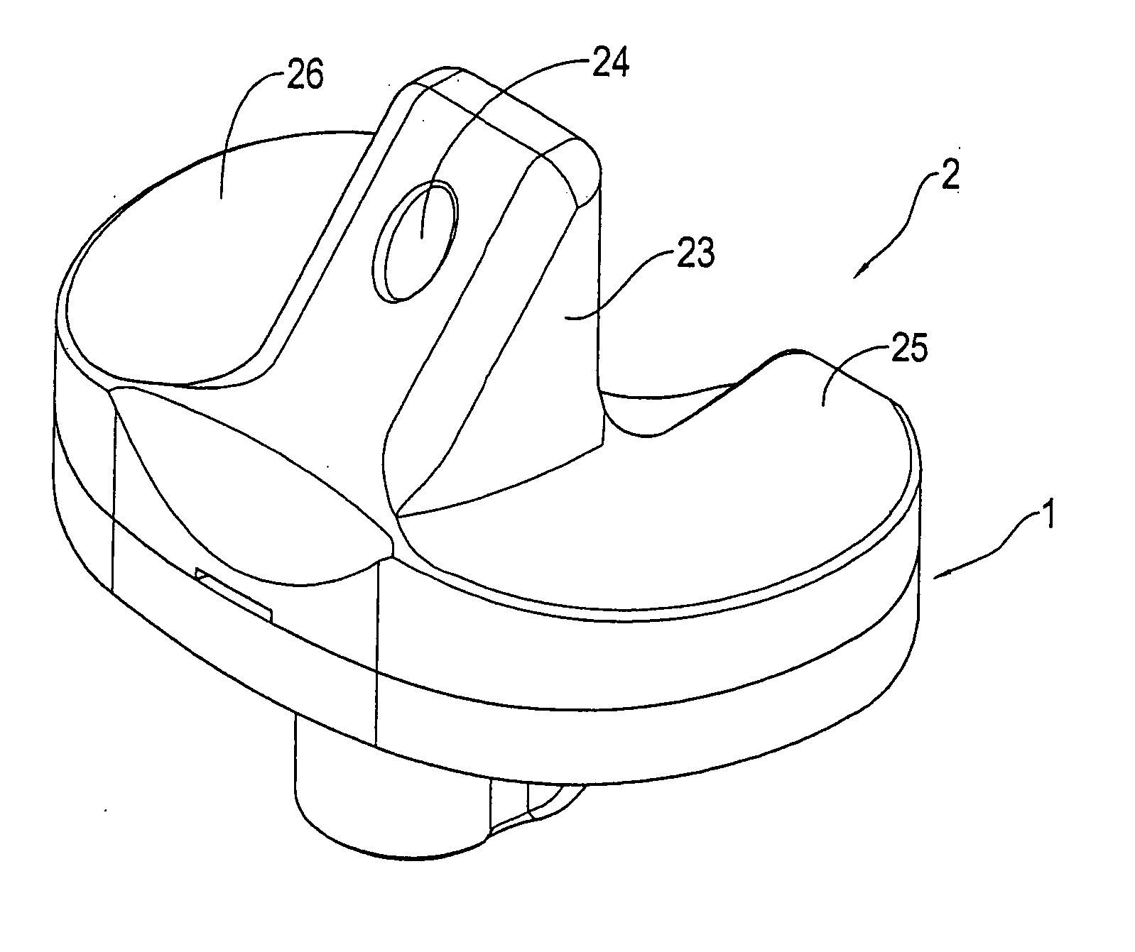
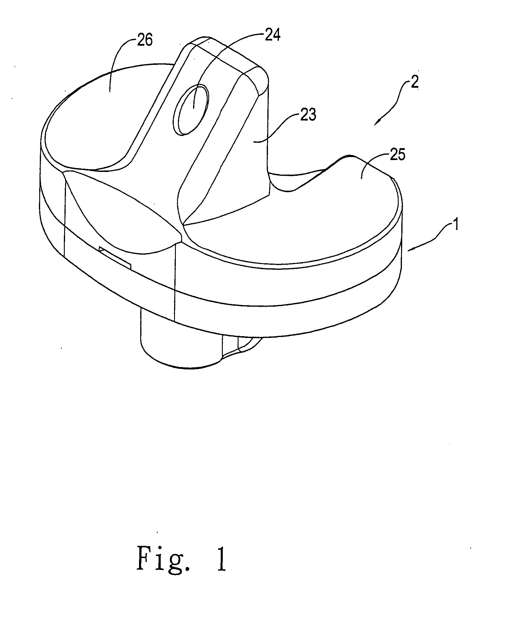
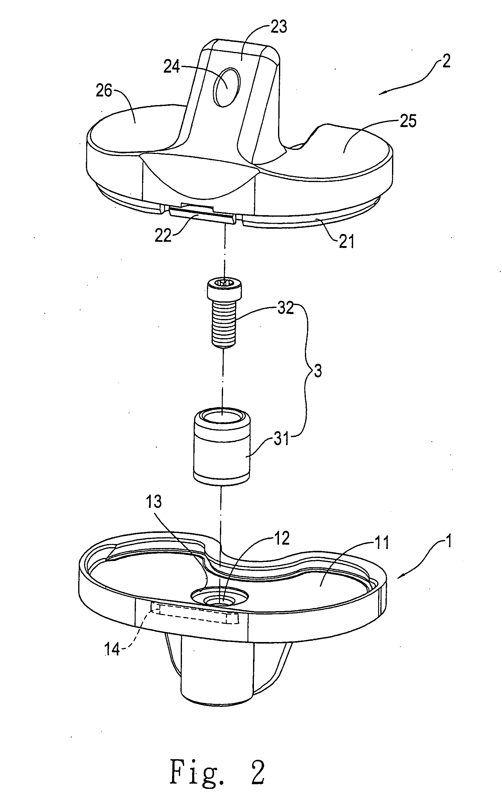
[0017]With reference to the drawings and in particular to FIGS. 1-3, which show, respectively, a perspective view, an exploded view, and a cross-sectional view of an orthopaedic implant constructed in accordance with the present invention, the orthopaedic implant of the present invention comprises a tibial baseplate 1, a tibial insert 2, and a reinforcement 3.

[0018]The tibial baseplate 1 is of a modular design having various sizes and forms a recess 11. The recess 11 has a bottom that defines, in a central portion thereof, a through hole 12 extending through the tibial baseplate 1. The through hole 12 has a top circumference that defines a circumferential groove 13 extending outward. The lower portion of the through hole 12 is coupled to a stem 4 (see FIG. 5), or an offset adaptor (not shown). The through hole 12 and the stem 4 or the offset adaptor have ends that are of inclination according to Morse taper. A side wall of the recess 11 defines a retention slot 14 for retaining enga...


PUM


Abstract

A structure improvement of orthopaedic implant includes a tibial baseplate, a tibial insert, and a reinforcement. The tibial baseplate forms a recess having a bottom that has a central portion defining a through hole extending through the tibial baseplate. The through hole has a top circumference that defines a circumferential groove extending outward. The tibial insert has a bottom forming a projection corresponding to the recess of the tibial baseplate for press-fitting to the tibial baseplate. A support is formed on at a central portion of a top of the tibial insert and defines a bore that extends through the tibial insert. The tibial insert forms two curved surfaces on opposite sides of the support to support contact and rolling. The reinforcement is inset in the tibial insert and includes a sleeve and a bolt.

Description

FIELD OF THE INVENTION[0001]The present invention relates to a structure improvement of orthopaedic implant, and in particular to an orthopaedic implant comprising a special design of reinforcement to enhance stable coupling between a tibial insert and a tibial baseplate to offer the advantages of resistance against external force, prevention of deformation, and extension of lifespan, and to be applicable to severe bone damage or second knee replacement surgery.BACKGROUND OF THE INVENTION[0002]Due to aging, joints of human beings may suffer wear or degradation caused by long term use or degeneration, leading to pain or incapability of providing proper moving functions, as a consequence of which daily living is affected. When a joint suffers severe pathological changes, artificial knee joint replacement provides a measure to release the pain and improve joint function. Artificial knee joint is often composed of components made of metal or plastics and can be fixed to bones to replace...

Claims


Application Information

Patent Timeline
IPC IPC(8): A61F2/38
CPCA61F2/3886
Inventor LU, CHENG-KUANGLIU, YU-LIANGLIAU, JIANN-JONG
Owner UNITED ORTHOPEDIC CORP
Why Eureka
Try Eureka