
Razor

a razor and blade technology, applied in the field of razors, can solve the problems of difficult to discharging debris outside the blade base, difficult to form elastic members and place members, and complicated structure of razors, so as to simplify the structure for supporting the blade body, improve shaving performance, and improve the effect of debris discharging function

Active Publication Date: 2010-06-24
KAI R&D CENT CO LTD
View PDF49 Cites 29 Cited by
  • Summary
  • Abstract
  • Description
  • Claims
  • Application Information

AI Technical Summary

Benefits of technology

[0017]In this instance, since a wide debris discharge hole is formed between the back opening and the front opening on the base, it is possible to improve the debris discharge function and simplify the structure for supporting the blade body.
[0018]It is preferable that in the above razor, each of the placing bodies is provided with a leaf spring, the blade body supporting portion is constructed between both leaf springs, and an urging force of both leaf springs elastically supports the blade body so as to be movable against a pressing force when contacting the skin surface. In this instance, the contact pressure of the blade body on the skin surface is restricted to improve the shaving performance.
[0019]It is preferable that in the above razor, both leaf springs are each provided with a pair of leg portions supported by both sides of the blade base member, and a space is provided between both leaf springs and the blade base member. In this instance, the structure of the leaf spring is simplified.
[0020]It is preferable that in the razor, the blade base member is provided with a base plate for supporting the base, and the base plate is made of a metal higher in ionization tendency than the base or the blade body. In this instance, since the base plate is oxidized before the blade body, it is possible to prevent the blade body from being rusted.

Problems solved by technology

Therefore, such a problem is posed that there is difficulty in discharging debris outside the blade base.
Further, in a structure where the blade body is held and supported between the blade-body placing member connected to the elastic member and the holding portion on the top plate, it is troublesome to form elastic members and placing members.
Still further, there is another problem of making the razor complicated in structure due to a mechanism for allowing the top plate to move together with the blade body.

Method used


Image

  • Razor
  • Razor
  • Razor

Examples


Embodiment Construction

[0041]Hereinafter, a description will be given of an embodiment of the present invention by referring to drawings. In explaining a razor of the present invention, X, Y, Z directions will be defined as shown in FIGS. 5 and 6.

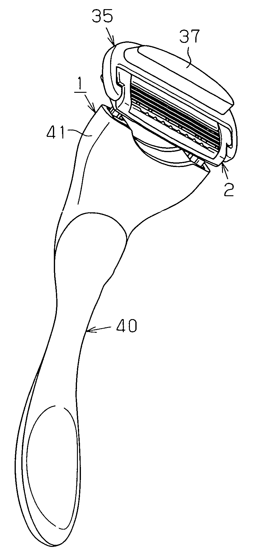
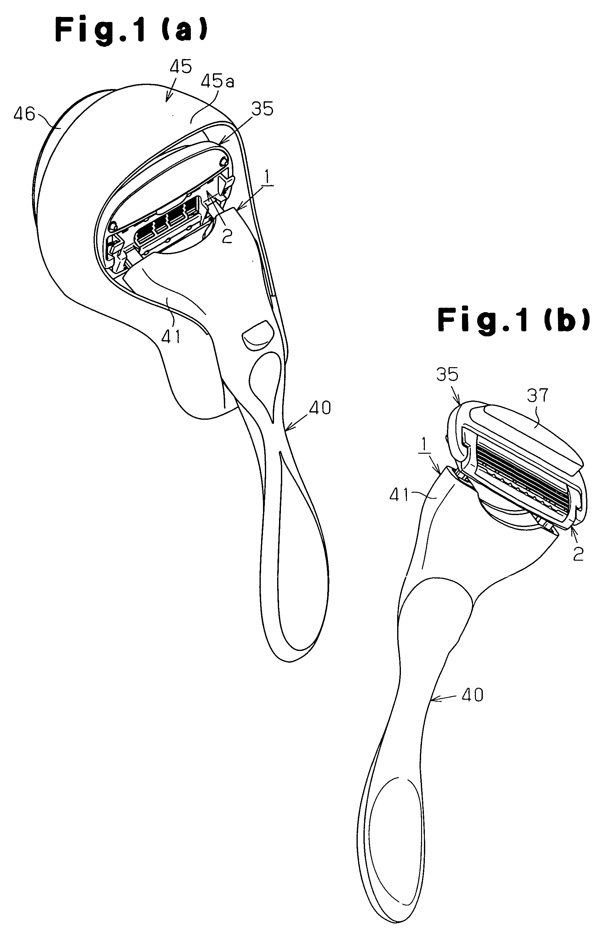
[0042]As shown in FIG. 1, an oscillating razor 1 is provided with a razor head 2.

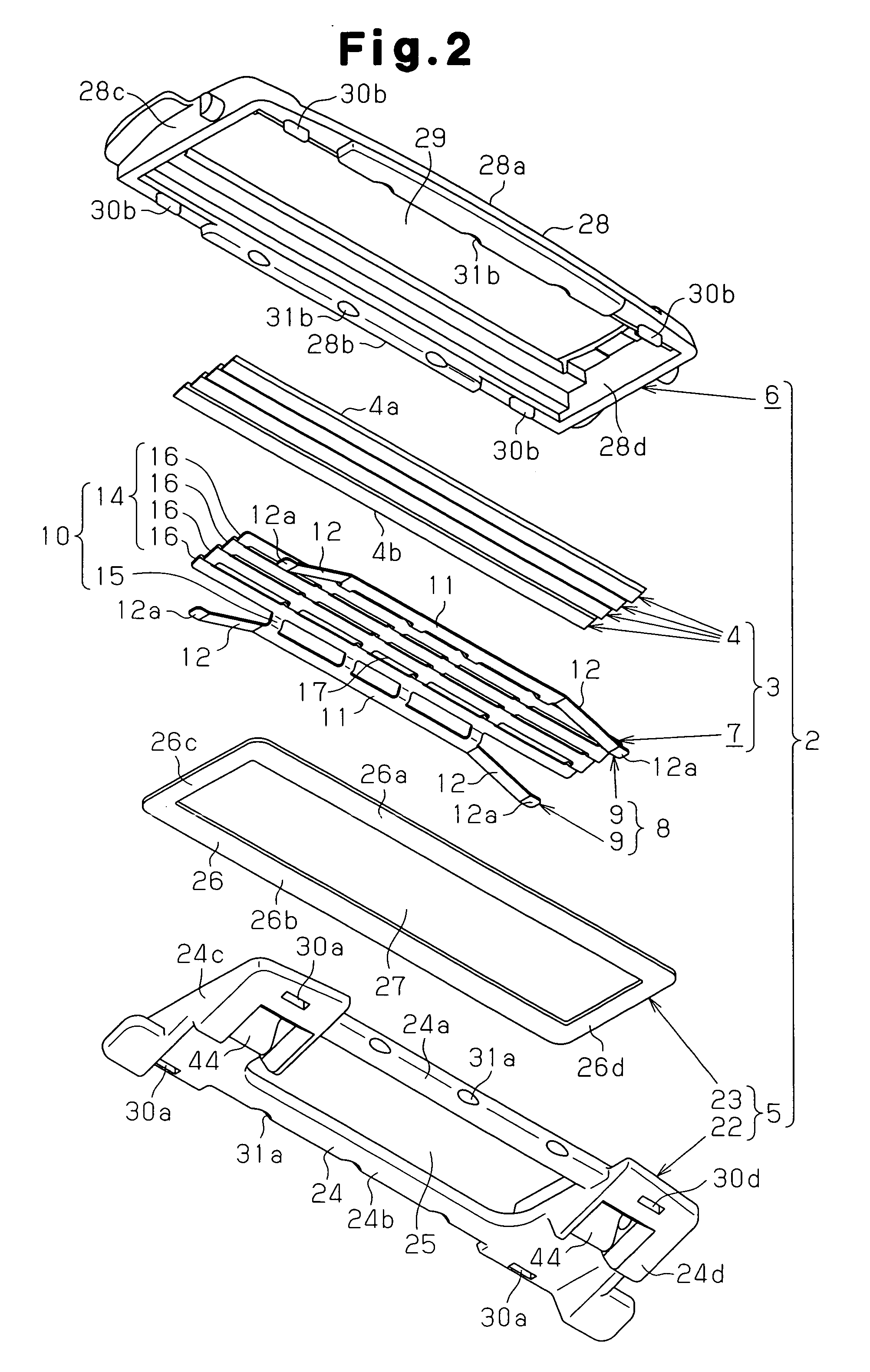
[0043]As shown in FIG. 2, the razor head 2 is provided with a blade member 3 made up of four blade bodies 4 and a base 7, a blade base member 5 arranged on the back side of the razor head 2, and a top member 6 arranged on the front side of the razor head 2. The blade body 4 is made of a metal such as martensite stainless steel. The thickness of the blade body 4 is set, for example, in a range between 0.05 mm and 0.3 mm, inclusive.

[0044]The base 7 is made of a metal such as austenite stainless steel. The base 7 is formed, for example, by press-working a metal plate having a thickness of 0.1 mm to 0.5 mm. The base 7 is provided with a placing base 8 as a placing body made up of a pair ...


PUM


Abstract

A razor head 2 is provided with a blade member 3 having a base and a blade body 4 on the base, a blade base member 5 arranged on the back side of the razor head 2, and a top member 6 arranged on the front side of the razor head 2. The blade member 3 is fitted between the blade base member 5 and the top member 6. The base of the blade member 3 is supported on the blade base member 5. A cutting edge 4a of the blade body 4 is exposed at the top member 6. The base is provided with a pair of leaf springs arranged between the blade base member 5 and the top member 6. A back opening 19 is disposed on the back side of the razor head 2 between both leaf springs, and a front opening 20 is disposed on the front side of the razor head 2. The base is provided with a debris discharge hole 18 between the front opening 20 and the back opening 19. The debris discharge hole 18 of the base is opened on the back side of the razor head 2 via the back opening 19 and also opened on the front side of the razor head 2 via the front opening 20.

Description

TECHNICAL FIELD[0001]The present invention relates to a razor provided with a razor head having a blade body and to a structure of a discharge hole disposed inside the razor head.BACKGROUND ART[0002]As disclosed in Patent Document 1, a movable blade-body type safety razor is provided with a frame body made up of a front guard, a pair of side frame portions, and a back frame portion on a blade base. Inside the frame body, arranged are a plurality of elastic arms and a plurality of blade-body placing members connected thereto. Of these blade-body placing members, a front blade body is arranged on a blade-body placing member on the front side, whereas a back blade body is arranged on a blade-body placing member on the back side. Both blade bodies are arranged inside the frame body and also held between a holding portion disposed on a top plate and the blade-body placing members. Therefore, both blade bodies are elastically supported on the blade base so as to be movable together with t...

Claims


Application Information

Patent Timeline
Patent Type & Authority Applications(United States)
IPC IPC(8): B26B21/40
CPCB26B21/227B26B21/4012B26B21/44B26B21/4068B26B21/4025
Inventor NAKASUKA, HIROYUKI
Owner KAI R&D CENT CO LTD
Learn More