
Subsea Force Generating Device and Method

Active Publication Date: 2010-06-24
HYDRIL USA DISTRIBUTION LLC
View PDF29 Cites 22 Cited by
  • Summary
  • Abstract
  • Description
  • Claims
  • Application Information

AI Technical Summary

Benefits of technology

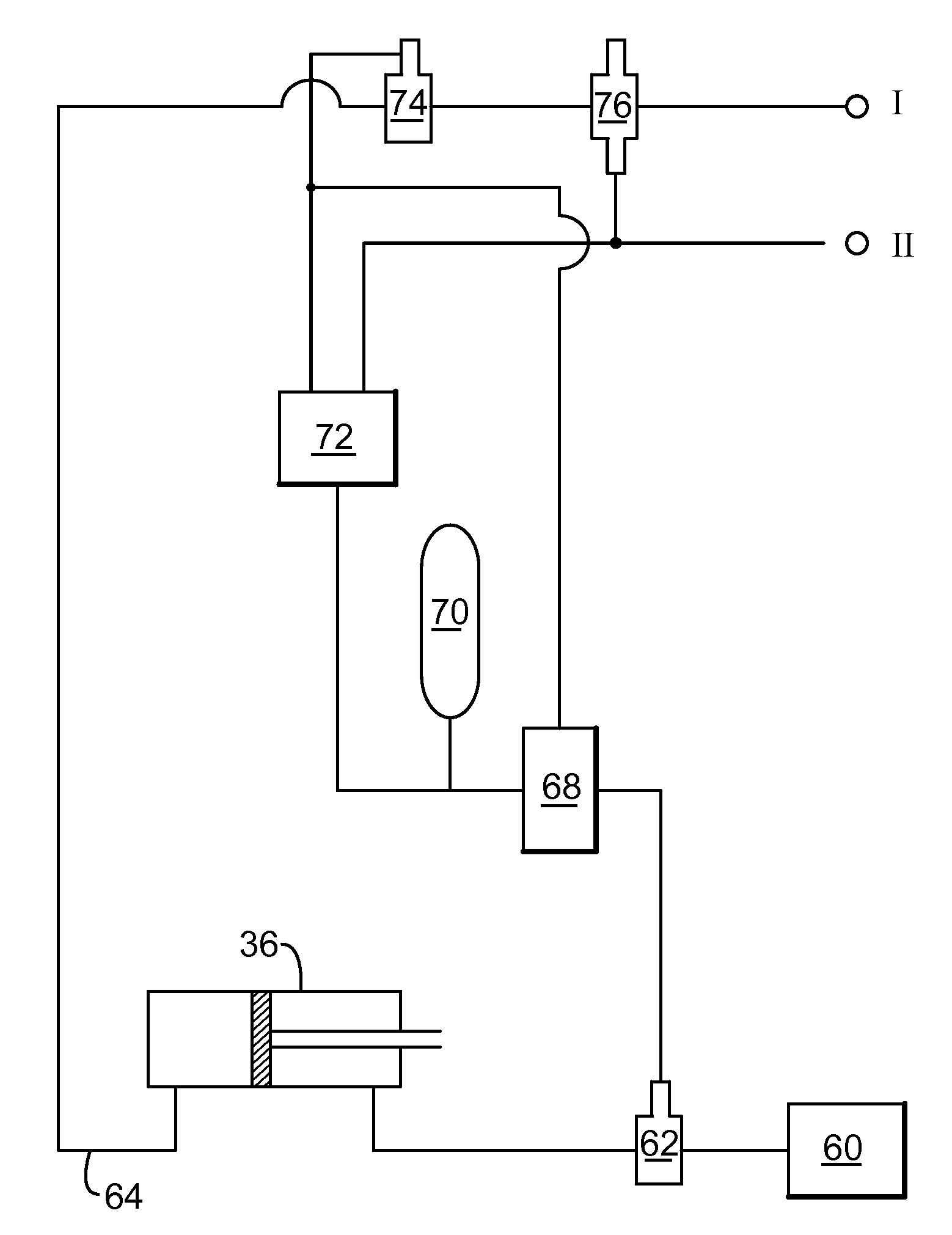
[0014]According to one exemplary embodiment, there is a water submerged device for generating a force under water. The device includes a low pressure recipient configured to contain a volume of a first fluid at a low pressure volume; an inlet connected to the low pressure recipient and configured to exchange a second fluid with an external enclosure; and a valve connected to the external enclosure and the inlet and configured to separate a pressure source in the external enclosure from the low pressure recipient. When the valve is open, such that there is a flow communication between the external enclosure and the low pressure recipient, a pressure imbalance occurs in the external enclosure which generates the force and the second fluid from the external enclosure enters the low pressure recipient and compresses the first fluid.
[0015]According to another exemplary embodiment, there is a method for generating a force by moving a piston inside an external enclosure of a water submerged device, the piston dividing the external enclosure into a closing chamber and an opening chamber and the opening chamber communicating with a low pressure recipient via a pipe having a valve, the valve separating a pressure source in the opening chamber from the low pressure recipient, and the low pressure recipient containing a volume of a first fluid. The method includes applying a first pressure to the closing and opening chambers, wherein the first pressure is generated by a weight of the water at a certain depth of the device; ap

Problems solved by technology

However, the availability of land-based production fields is limited.
However, a common feature of these systems is their limited operation depth.
However, during normal drilling operation, unexpected events may occur that could damage the well and / or the equipment used for drilling.
One such event is the uncontrolled flow of gas, oil or other well fluids from an underground formation into the well.
This event is unforeseeable and if no measures are taken to prevent it, the well and / or the associated equipment may be damaged.
Another event that may damage the well and / or the associated equipment is a hurricane or an earthquake.
Both of these natural phenomena may damage the integrity of the well and the associated equipment.
For example, due to the high winds produced by a hurricane at the surface of the sea, the vessel or the rig that powers the undersea equipment starts to drift resulting in breaking the power / communication cords or other elements that connect the well to the vessel or rig.
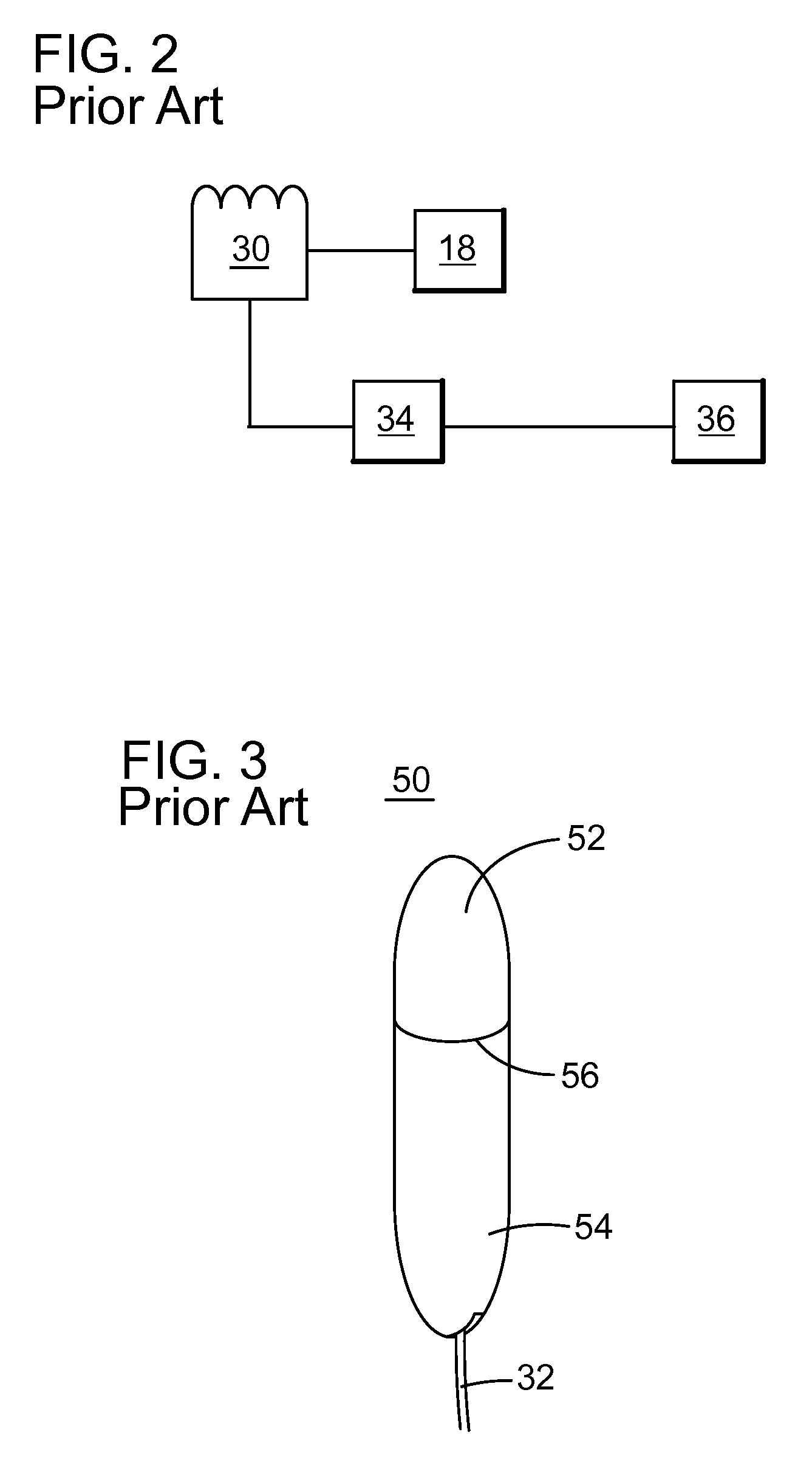
Typical accumulators are charged with nitrogen but as precharge pressures increase, the efficiency of nitrogen decreases which adds additional cost and weight because more accumulators are required subsea to perform the same operation on the surface.
For example, a 60-liter (L) accumulator on the surface may have a useable volume of 24 L on the surface but at 3000 m of water depth the usable volume is less than 4 L. To provide that additional pressure deep undersea is expensive, the equipment for providing the high pressure is bulky, as the size of the canisters that are part of the accumulator 30 is large, and the range of operation of the BOPs is limited by the initial pressure difference between the charge pressure and the hydrostatic pressure at the depth of operation.
Therefore, the use of pressured canisters to store high-pressure fluids to operate a BOP make the operation of the offshore rig expensive and require the manipulation of large parts.
When the valve is open, such that there is a flow communication between the external enclosure and the low pressure recipient, a pressure imbalance occurs in the external enclosure which generates the force and the second fluid from the external enclosure enters the low pressure recipient and compresses the first fluid.

Method used


Image

  • Subsea Force Generating Device and Method
  • Subsea Force Generating Device and Method
  • Subsea Force Generating Device and Method

Examples


Embodiment Construction

[0030]The following description of the exemplary embodiments refers to the accompanying drawings. The same reference numbers in different drawings identify the same or similar elements. The following detailed description does not limit the invention. Instead, the scope of the invention is defined by the appended claims. The following embodiments are discussed, for simplicity, with regard to the terminology and structure of BOP systems. However, the embodiments to be discussed next are not limited to these systems, but may be applied to other systems that require the supply of force when the ambient pressure is high such as in a subsea environment.

[0031]Reference throughout the specification to “one embodiment” or “an embodiment” means that a particular feature, structure, or characteristic described in connection with an embodiment is included in at least one embodiment of the subject matter disclosed. Thus, the appearance of the phrases “in one embodiment” or “in an embodiment” in ...


PUM


Abstract

Method and water submerged device for generating a force under water. The device includes a low pressure recipient configured to contain a volume of a first fluid at a low pressure volume, an inlet connected to the low pressure recipient and configured to exchange a second fluid with an external enclosure, and a valve connected to the external enclosure and the inlet and configured to separate a pressure source in the external enclosure from the low pressure recipient. When the valve is open, such that there is a flow communication between the external enclosure and the low pressure recipient, a pressure imbalance occurs in the external enclosure which generates the force and the second fluid from the external enclosure enters the low pressure recipient and compresses the first fluid.

Description

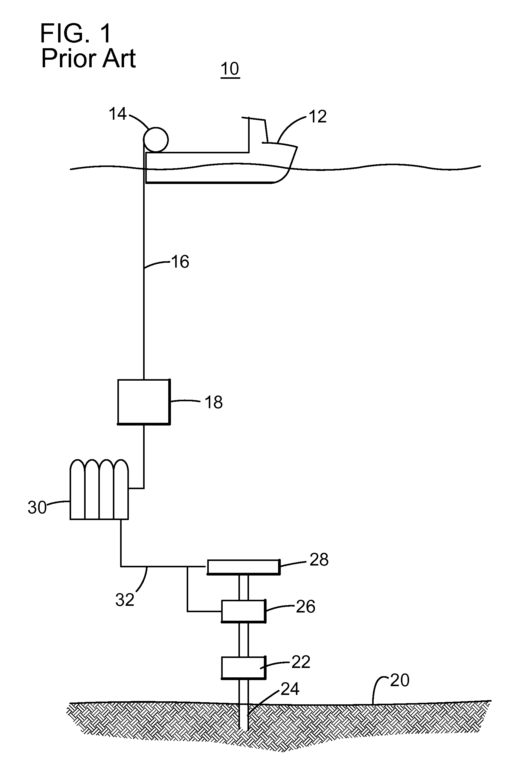
BACKGROUND[0001]1. Technical Field[0002]Embodiments of the subject matter disclosed herein generally relate to methods and systems and, more particularly, to mechanisms and techniques for generating a subsea force.[0003]2. Discussion of the Background[0004]During the past years, with the increase in price of fossil fuels, the interest in developing new production fields has dramatically increased. However, the availability of land-based production fields is limited. Thus, the industry has now extended drilling to offshore locations, which appear to hold a vast amount of fossil fuel.[0005]The existing technologies for extracting the fossil fuel from offshore fields use a system 10 as shown in FIG. 1. More specifically, the system 10 includes a vessel 12 having a reel 14 that supplies power / communication cords 16 to a controller 18. A Mux Reel may be used to transmit power and communication. Some systems have hose reels to transmit fluid under pressure or hard pipe (rigid conduit) to ...

Claims


Application Information

Patent Timeline
IPC IPC(8): E21B23/00E21B33/064E21B33/06E21B23/04E21B41/00
CPCE21B33/0355E21B33/06F15B21/006E21B33/064E21B33/063
Inventor GUSTAFSON, RYAN
Owner HYDRIL USA DISTRIBUTION LLC
Learn More