Pilot-controlled valve having a ceramic control piston

a technology of control piston and pilot valve, which is applied in the direction of multiple way valve, valve details, thin material handling, etc., can solve the problems of elastomeric seals that are sensitive to pressure media, sealing sleeves that give rise to particularly great erosive wear, and reduce sealing effect, etc., to achieve simple and cost-effective production and great sealing behavior

Inactive Publication Date: 2010-06-24
KNORR-BREMSE SYST FUER NUTZFAHRZEUGE GMBH
View PDF9 Cites 4 Cited by
  • Summary
  • Abstract
  • Description
  • Claims
  • Application Information

AI Technical Summary

Benefits of technology

[0004]The present invention is therefore based on the object of further developing a valve that is able to have pilot control, of the type mentioned at the outset, in such a way that it has great sealing behavior over a long time period, and at the same time is simple and cost-effective to produce.

Problems solved by technology

However, after some time, such an elastomeric seal demonstrates subsiding phenomena, so that the sealing effect decreases.
Furthermore, such an elastomeric seal is sensitive to pressure media that are contaminated by particles.
This disadvantage is of greater consequence if, as is the case here, the valve has to cope with large flow volumes, and the sealing sleeve is situated directly in the flow region of the pressure medium, because then the exposure to particles of the sealing sleeve gives rise to particularly great erosive wear.

Method used


Image

  • Pilot-controlled valve having a ceramic control piston
  • Pilot-controlled valve having a ceramic control piston
  • Pilot-controlled valve having a ceramic control piston

Examples


Embodiment Construction

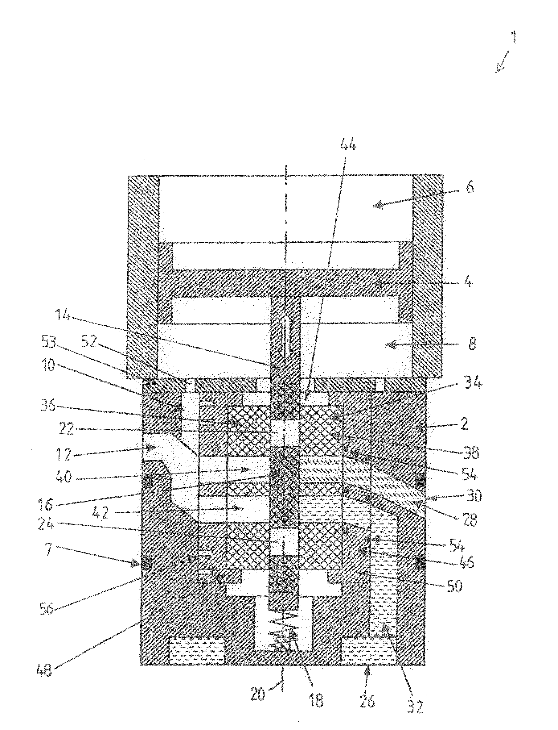
[0031]According to one particularly specific embodiment, the pilot-controlled valve is a pressure-regulating valve for an air pressure braking system of a vehicle. According to the specific embodiment of FIG. 1, pressure-regulating valve 1 has an insert 2, accommodated from a housing that is not shown, in whose axial direction a linearly movable control piston 4 is supported, which may be controlled by an electromagnetic valve, not shown, by the pressure increase, pressure maintenance and pressure decrease of compressed air located in a control chamber 6 that is bordered by control piston 4. Insert 2 is developed to be insertable in the housing, and is sealed, which may be by O-rings, from an inner wall of the housing, by seals 7. Since insert 2 represents a static element as opposed to moving parts of valve 1, it will be regarded as belonging to the housing, in the following text.

[0032]Beyond control chamber 6, control piston 4 borders on a working chamber 8, which is in connection...


PUM


Abstract

A pilot-controlled valve, having a valve system which switches a pressure medium flow between at least one working connection, a supply pressure connection and a ventilation connection. The invention provides that the valve system includes at least one valve member made of ceramic material that is operated rotationally and/or linearly by the pilot control, at least one connecting channel is developed in the valve member which is able to be brought into flow connection to the working connection, which, as a function of the position of the valve member, produces a flow connection of the working connection to a first flow channel that is in connection to the ventilation connection or to a second flow channel that is in connection to the supply pressure connection, at least one section of the first flow channel and the second flow channel being developed in at least one static valve body that is made of ceramic material, at least the first flow channel is sealed from the second flow channel by at least one seal that is situated in a region outside a direct inflow by the pressure medium.

Description

FIELD OF THE INVENTION[0001]The present invention relates to a pilot-controlled valve, having a valve configuration which switches a pressure medium flow between at least one working connection, a supply pressure connection as well as a ventilation connection.BACKGROUND INFORMATION[0002]A pilot-controlled valve is discussed in DE 101 20 322 C1, and relates to a pressure-regulating valve of a compressed air braking system of a motor vehicle, for the purpose of regulating a brake pressure corresponding to a braking pressure setpoint value. The regulating valve has a control piston that is accommodated within a valve housing, which is able to be operated linearly via a control chamber. Opposite the control chamber, the control piston borders on a working chamber. From the working chamber, a coaxial hollow pin is developed on the control piston which is used for the operation of a valve seat system. The valve seat system includes a double seat valve, a valve member actuated by the contr...

Claims


Application Information

Patent Timeline
Patent Type & Authority Applications(United States)
IPC IPC(8): F16K31/12
CPCF16K11/06F16K31/043F16K31/363Y10T137/8663Y10T137/86638Y10T137/86694
Inventor WOERNER, RALFDEJA, SIEGMUND
Owner KNORR-BREMSE SYST FUER NUTZFAHRZEUGE GMBH
Why Eureka
Try Eureka