Wheelchair Lever Drive System

a technology of lever drive and wheel chair, which is applied in the direction of rider propulsion, vehicle components, ambulance service, etc., can solve the problems of limiting the general acceptance of potential users, requiring considerable grip strength, repetitive motion injuries, etc., and achieves improved directional control shifting biomechanics, reduced user training period, and more confident control of wheelchairs

Inactive Publication Date: 2010-06-24
GREEN STEVE
View PDF12 Cites 22 Cited by
  • Summary
  • Abstract
  • Description
  • Claims
  • Application Information

AI Technical Summary

Benefits of technology

[0013]The present invention furthers the state of the art by providing a lever propulsion direction selection means for manual wheelchairs that allows improved biomechanics of directional control shifting, forward / reverse and reverse / forward. Operator directional control input through the pivoting of the propulsion lever handgrip uses intuitive pivoting motions which result in a reduced user training period and more confident control of the wheelchair. Precise control of wheelchair positioning is further improved by incorporation of simple brake operation means into the handgrip interface as a rotation of the handgrip.
[0014]This pivoting handgrip directional shifting combined with brake operation by handgrip rotation allows the operator to maintain a non-changing- hand grip position such that propulsion movement of the levers may be comfortably simultaneous with direction shifting and braking.OBJECTS OF THE INVENTION

Problems solved by technology

Although such means of propelling is simple, light in weight, and inexpensive, problems with pushrims include placing the users hand near the tires of the driving wheels which may be dirty, requiring considerable grip strength to grasp the pushrim, and repetitive motion injuries from the non-optimal bio-mechanics of grasping and pushing the pushrims.
To this point in the state of the art, lever drive mechanisms have all had deficiencies that limit general acceptance by potential users.
These deficiencies include being too heavy, too bulky, having non-ergonomic forward / reverse shifting control inputs, and being obtrusive in appearance.
This style of lever drive is exceptionally obtrusive in appearance, needlessly heavy, and has not been accepted by the user community.
Although potentially less obtrusive than the forward mount lever arrangement discussed above, the bulky physical size of current hub mount lever drive mechanisms causes them to be placed on the outside of the driving wheel, and thus are still objectionably obtusive.
Additionally, this placement causes the width of the wheelchair to increase, which is problematic for passing through typical doorways.
This results in an awkwardly large angle through which the user must rotate the handgrip in order to affect change of direction, forward / reverse or reverse / forward shifts.
This condition significantly impairs the user experience, and predisposes users to forego using a lever drive wheelchair, other benefits notwithstanding.
This results in an expensive clutch and control arrangement, not well suited to low production uses such as wheelchairs.
Various roller clutch mechanisms are known to the art, but fail to adequately address wheelchair lever drive needs.
This type of clutch is complex and problematically expensive to manufacture in small quantities for wheelchair applications.
Due to the dependence on individual springs for roller biasing, the arrangement thus taught is limited to a bi-state operation, as the springs will push the rollers either one direction on the other, and are not intended or able to achieve an intermediate position.
This arrangement as presented is of greater complexity and cost than is needed for wheelchair transmissions.
This arrangement is inherently biomechanically sub-optimal, in that it requires an unnecessarily large flexure of the wrist during the push / pull propulsion motion.
Additionally, by using a rotation of the grip interface to effect forward / reverse shifting, it further causes the user wrists to be placed at non-optimal angles relative to the stress of pushing and pulling for propulsion.
However, the specific biomechanical challenges of manual wheelchair propulsion by lever drive have not adequately addressed by the state of the art.

Method used


Image

  • Wheelchair Lever Drive System
  • Wheelchair Lever Drive System
  • Wheelchair Lever Drive System

Examples


Embodiment Construction

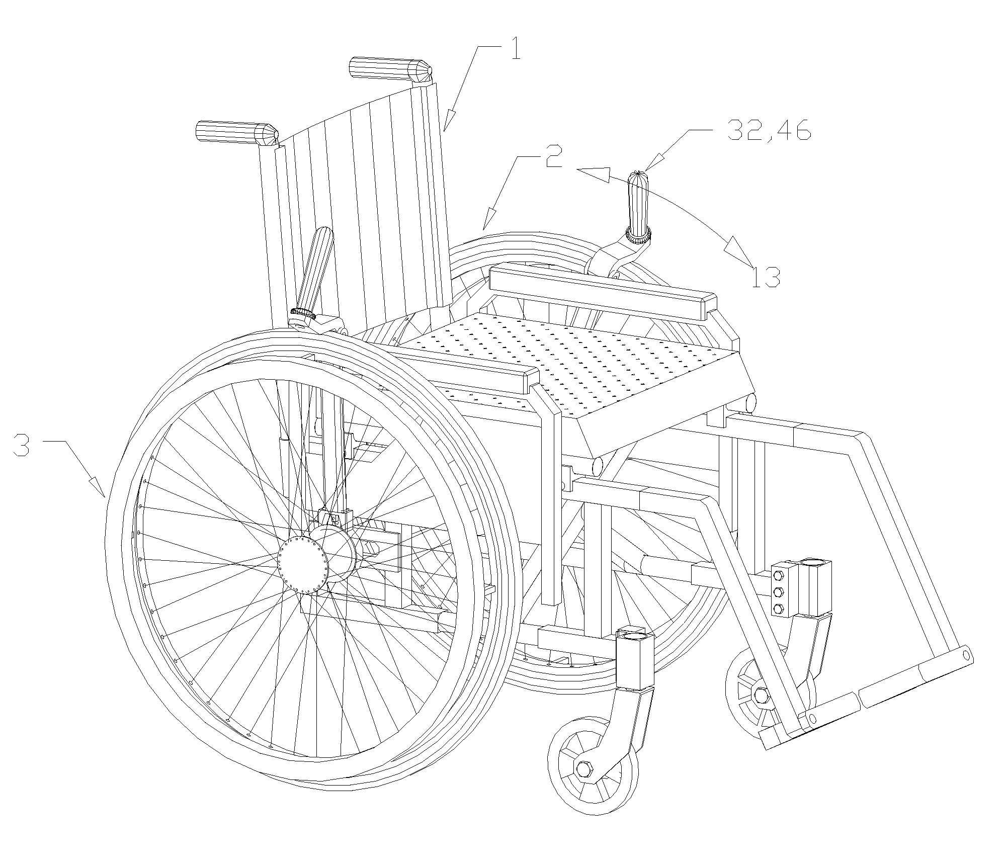
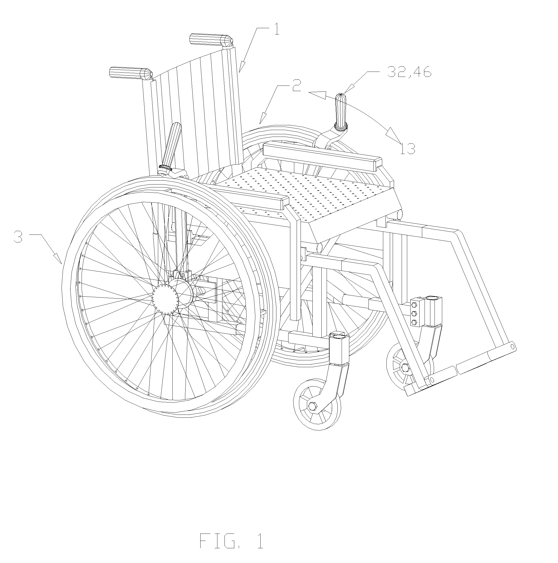
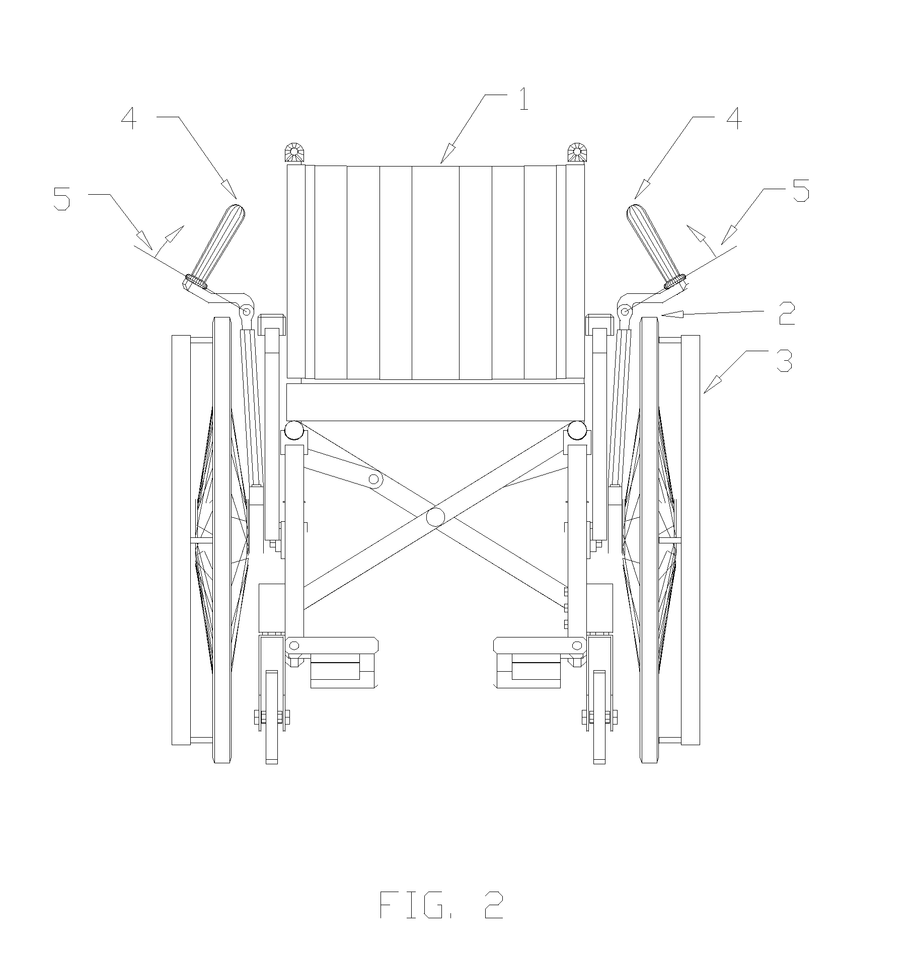
[0037]With reference to FIGS. 1 through 3, a typical wheelchair 1 is shown with a preferred embodiment of the wheelchair lever drive system installed on a typical wheelchair frame. It can be seen that propulsion lever assemblies 32 are placed to the inside of rear drive wheels 2. This position is preferable to outside placement as it allows handgrip assemblies 46 to be closer together side-to-side in an ergonomically advantageous position and does not increase the overall width of the wheelchair. It also makes the overall lever drive mechanism aesthetically less obtrusive, a feature shown by independent survey to be important to users. Lever propulsion motion arrows 13 indicate the approximate arc of reciprocating motion that the user would impart to lever assemblies 32 when propelling wheelchair 1.

[0038]With reference to FIGS. 3A, 3B, and 3C, a wheelchair user would grasp grip 4 and push or pull, thus imparting a propelling motion shown by arrow 13, and could, as desired, impart a ...


PUM


Abstract

A manual propulsion mechanism for wheelchairs utilizes a lever pivotally mounted to the hub of each rear wheel such that the wheelchair user can propel the chair with push / pull movements of the levers. Forward and reverse propulsion directions are accomplished by a system of one-way reversible clutches contained in the propulsion wheel hubs which also allow the levers to be operationally disconnected such that the chair can freewheel. Operator control of direction shifting is through pivoting motions imparted to the grip handles of the propulsion levers. In a preferred embodiment, improved ergonomics for propulsion direction changes are made possible by coordinating the direction of the shift pivot motion with the push / pull movement of the levers. This allows the operator to retain a comfortable, stable grip on the grip handle while simultaneously propelling and controlling direction of movement.

Description

CROSS-REFERENCE TO RELATED APPLICATIONS[0001]Not ApplicableSTATEMENT REGARDING FEDERALLY SPONSORED R&D[0002]Not ApplicableREFERENCE TO SEQUENCE LISTING OR COMPUTER PROGRAM[0003]Not Applicable[0004]This invention relates to manual wheelchair drive mechanisms.BACKGROUND OF THE INVENTION[0005]Wheelchairs are typically intended to provide independent mobility for persons without the use of their legs, and provide means of utilizing arm movement to cause rotation of one or more wheels of the wheelchair. In the commonest and simplest form, round pushrims of slightly smaller diameter than the propelling wheels are fixed to the said propelling wheels, such that the user may conveniently grasp the pushrims to exert a rotational torque to the driving wheels through the pushrims. Although such means of propelling is simple, light in weight, and inexpensive, problems with pushrims include placing the users hand near the tires of the driving wheels which may be dirty, requiring considerable grip...

Claims


Application Information

Patent Timeline
Patent Type & Authority Applications(United States)
IPC IPC(8): B62M1/16
CPCA61G5/025A61G5/023
Inventor GREEN, STEVE C.
Owner GREEN STEVE
Why Eureka
Try Eureka