Complementary permanent magnet structure capable of minimizing cogging torque for rotating electric machine

a permanent magnet and electric machine technology, applied in the direction of magnetic circuits, electrical apparatus, dynamo-electric machines, etc., can solve the problems of not only but also reducing the effective output magnetic torque, etc., to achieve the effect of minimizing the cogging torqu

Active Publication Date: 2010-06-24
IND TECH RES INST
View PDF14 Cites 23 Cited by
  • Summary
  • Abstract
  • Description
  • Claims
  • Application Information

AI Technical Summary

Benefits of technology

[0014]It is an object of the present invention to provide to a complementary permanent magnet structure capable of minimizing the cogging torque for a rotating electric machine such as an electric motor or a power generator.

Problems solved by technology

When the driving torque is not much larger than the cogging torque, an undesired output torque ripple is generated to cause vibration and noise and further affect the control precision, especially when rotating at a very low rate.
Reducing the equivalent magnetic flux in the air gap does not only minimize the cogging torque but also reduce the effective output magnetic torque.
Therefore, such a method is seldom used to minimize the cogging torque.
However, such a method using skew rotation results in increased cost and time in manufacturing, assembly and inspection.
Using such a specific ratio, restricted windings are required and, sometimes, undesired radial forces occur.
For example, for a rotating electric machine comprising 9 slots and 8 magnetic poles, a radial force occurs for such a slot-to-pole ratio, which causes radial loading on the bearing and leads to vibration and noise.
Therefore, such a method is not suitable for low-vibration and low-noise applications.
However, such a design is only useful for a rotating electric machine really requiring multiple magnetic pole cores or multiple armature cores.
Moreover, such a design results in increased cost and time in manufacturing, assembly and inspection.

Method used


Image

  • Complementary permanent magnet structure capable of minimizing cogging torque for rotating electric machine
  • Complementary permanent magnet structure capable of minimizing cogging torque for rotating electric machine
  • Complementary permanent magnet structure capable of minimizing cogging torque for rotating electric machine

Examples


first embodiment

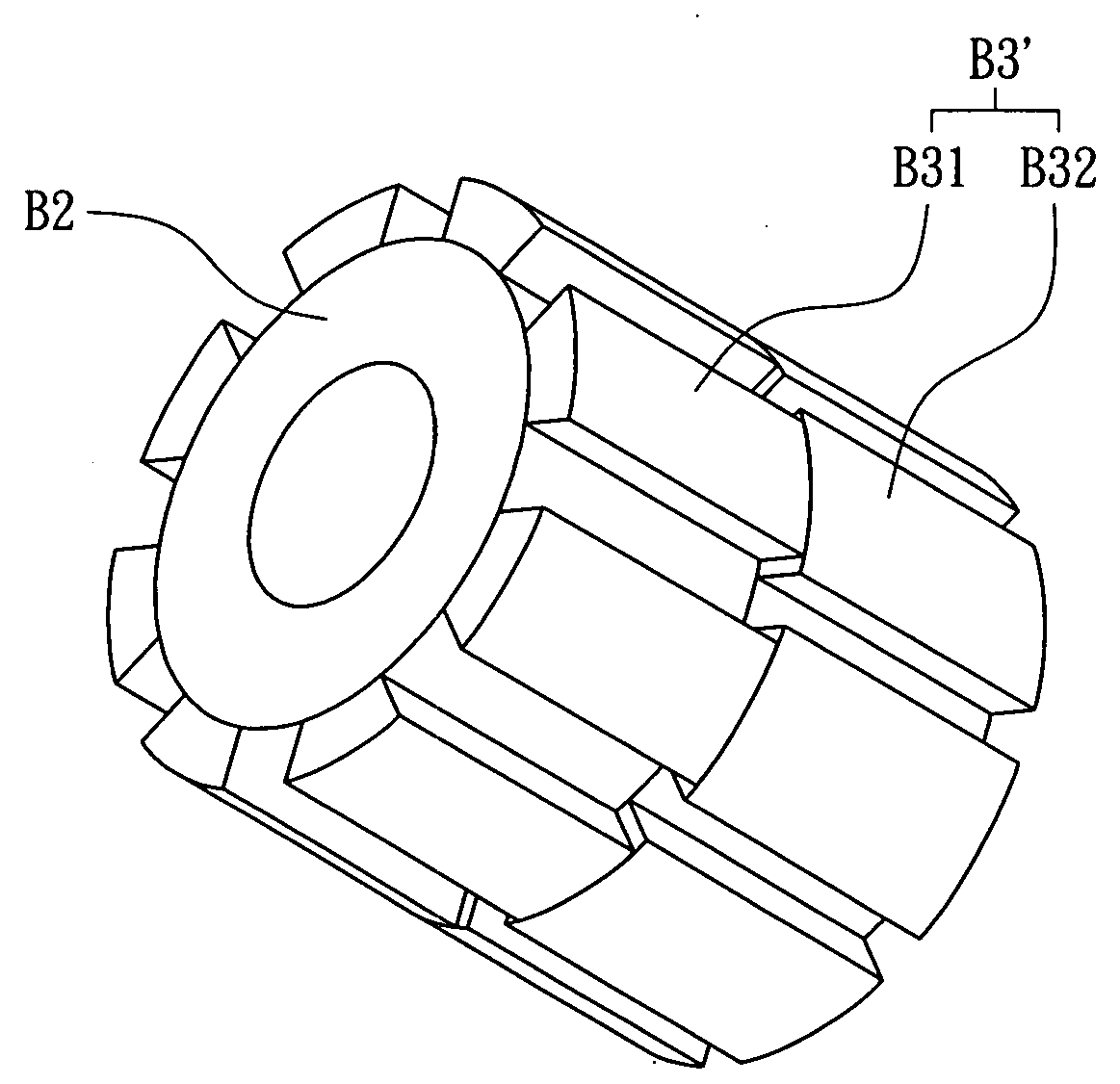
[0040]The total expanding angle (A3+A4) of the first permanent magnet unit set B31 is smaller than 360 degrees divided by the number of the slots S, and the total expanding angle (A5+A6) of the second permanent magnet unit set B32 is larger than 360 degrees divided by the number of the slots S. Therefore, two cogging torques with similar waveforms and 180 degrees of electrical angle difference are determined. Moreover, the two cogging torques can be identical by adjusting the thickness D3 of the first permanent magnet unit B31 and the thickness D4 of the second permanent magnet unit B32. In other words, the two cogging torques can be counterbalanced to be minimized by the complementary permanent magnet structure, as shown in FIG. 7. In FIG. 7, comparison of cogging torque to expanding electrical angle relations of permanent magnets according to the present invention is shown, wherein the cogging torque in the longitudinal axis is normalized and the rotating angle is expanded as 180 ...

second embodiment

[0044]Please refer to FIG. 13, which shows comparison of cogging torque to expanding electrical angle relations of the present invention and the prior art. In FIG. 13, the cogging torque in the longitudinal axis is normalized and the rotating angle is expanded as 180 degree electric angle in the transversal axis. In the present embodiment, the peak value of the cogging torque is reduced by 70% to achieve minimized cogging torque of the rotating electric machine.

[0045]Accordingly, the present invention discloses a complementary permanent magnet structure capable of minimizing the cogging torque for a rotating electric machine such as an electric motor or a power generator with ordinary manufacturing processing without additional manufacturing cost and time. Therefore, the present invention is novel, useful, and non-obvious.


PUM


Abstract

A complementary permanent magnet structure capable of minimizing the cogging torque for a rotating electric machine, the complementary permanent magnet structure comprising: a magnetic pole core being cylinder shaped with even numbered arc-shaped magnetic sets positioned with equal distances on the circumference thereof, each magnetic set being composed of a first permanent magnet unit and a second permanent magnet unit; and an armature core being ring shaped with a plurality of slots; wherein the ratio of the number of the slots to the number of magnetic poles of the magnetic pole core is 3 / 2; wherein the first permanent magnet unit and the second permanent magnet unit are positioned correspondingly to generate two complementary cogging torques with 180 degrees of electrical angle difference.

Description

1. FIELD OF THE INVENTION[0001]The present invention generally relates to a permanent magnet structure for an electric machine and, more particularly, to a complementary permanent magnet structure capable of minimizing the cogging torque for a rotating electric machine such as an electric motor or a power generator.2. BACKGROUND OF THE INVENTION[0002]In order to enhance the efficiency, increase the power density and minimize the relative size of a rotating electric machine (such as an electric motor and a power generator), a permanent magnet is used as a constant magnetic source. With the development in processing and materials, the permanent magnet with high magnetic energy product is widely used in rotating electric machines.[0003]When a permanent magnet is used as a constant magnetic source rotating without a load, the characteristics in the magnetic flux path of the rotating electric machine are controlled by the constant magnetic field. During rotation, the equivalent magnetic ...

Claims


Application Information

Patent Timeline
Patent Type & Authority Applications(United States)
IPC IPC(8): H02K21/14
CPCH02K21/16H02K2201/06H02K29/03
Inventor HUNG, SHIH-WEI
Owner IND TECH RES INST
Why Eureka
Try Eureka